


WAGO-I/O-SYSTEM 750
I/O Modules 355
750-882 Media Redundancy ETHERNET Controller
Manual
1.5.0
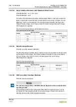
The above SSI Transmitter Interface modules have a total of 4 bytes of user data
in the Input Process Image, which has 2 words mapped into the image.
Word alignment is applied.
Table 400: SSI Transmitter Interface Modules
Input Process Image
Offset
Byte Destination
Description
High Byte
Low Byte
0
D1
D0
Data bytes
1
D3
D2
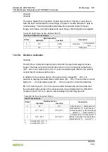
13.2.5.7 Incremental Encoder Interface Modules
750-631/000-004, -010, -011
The above Incremental Encoder Interface modules have 5 bytes of input data
and 3 bytes of output data. The following tables illustrate the Input and Output
Process Image, which have 4 words into each image. Word alignment is applied.
Table 401: Incremental Encoder Interface Modules 750-631/000-004, --010, -011
Input Process Image
Offset
Byte Destination
Description
High Byte
Low Byte
0
-
S
not used
Status byte
1
D1
D0
Counter word
2
-
-
not used
3
D4
D3
Latch word
Output Process Image
Offset
Byte Destination
Description
High Byte
Low Byte
0
-
C
not used
Control byte
1
D1
D0
Counter setting word
2
-
-
not used
3
-
-
not used
750-634
The above Incremental Encoder Interface module has 5 bytes of input data (6
bytes in cycle duration measurement mode) and 3 bytes of output data. The
following tables illustrate the Input and Output Process Image, which has 4 words
mapped into each image. Word alignment is applied.