Manual
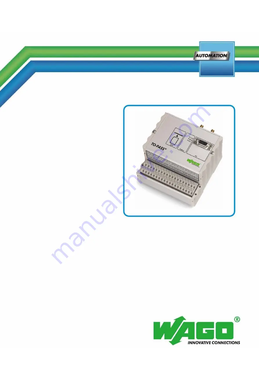
WAGO-TO-PASS® 761
TO-PASS® Mobile, 4 AI, Web, MODBUS
761-316
Telecontrol module for fault detection/indication,
position monitoring and remote control
Version 2.0.0
Страница 1: ...Manual WAGO TO PASS 761 TO PASS Mobile 4 AI Web MODBUS 761 316 Telecontrol module for fault detection indication position monitoring and remote control Version 2 0 0...
Страница 2: ...0 571 8 87 5 55 Fax 49 0 571 8 87 85 55 E Mail support wago com Every conceivable measure has been taken to ensure the accuracy and completeness of this documentation However as errors can never be fu...
Страница 3: ...2 2 4 Block Rounding for GPRS Connections 12 2 5 Safety Advice Precautions 13 3 Device Description 16 3 1 Scope of Delivery 16 3 2 Use 16 3 3 View 18 3 4 Connectors 19 3 4 1 GSM Antenna 19 3 4 2 GPS A...
Страница 4: ...ement 40 5 2 3 2 Voltage Measurement 41 5 2 4 Digital Outputs 42 5 2 5 MODBUS Interface 43 5 2 5 1 Serial Interface for MODBUS and PC 43 5 2 5 2 MODBUS RS 485 Network 44 6 Commissioning 45 6 1 Install...
Страница 5: ...6 8 5 Displaying the Data Logger DSP 97 8 6 Displaying the Event Logger ESP 98 9 Diagnostics 99 9 1 Test Inputs and Outputs 99 9 2 Testing the Counter Inputs 100 9 3 Testing the Connection 101 9 4 Tes...
Страница 6: ...0 0 10 3 2 2 3 Example for Logger Script Extension 119 10 3 2 3 Logger Script FW 2 33 Counter Inputs 121 10 3 2 3 1 Data Format of an LCDx Variable 121 10 3 2 4 Time Request Script FW 2 33 123 10 4 H...
Страница 7: ...ntation This documentation is only applicable to the telecontrol module 761 316 TO PASS Mobile 4 AI Web MODBUS In this manual the description of the operation software refers to the operation software...
Страница 8: ...tes a moderate risk potentially hazardous situation which if not avoided could result in death or serious injury Personal Injury Indicates a low risk potentially hazardous situation which if not avoid...
Страница 9: ...Notes about this Documentation 9 761 316 TO PASS Mobile 4 AI Web MODBUS Manual Version 2 0 0 Additional Information Refers to additional information which is not an integral part of this documentation...
Страница 10: ...ta files are marked in italic type e g C Programme WAGO I O CHECK Menu Menu items are marked in bold letters e g Save A greater than sign between two names means the selection of a menu item from a me...
Страница 11: ...utomation The specialists must be familiar with the current norms and guidelines for the devices and automated environments All changes to the controller should always be carried out by qualified pers...
Страница 12: ...o KG has no involvement with these types of problems Therefore WAGO Kontakttechnik GmbH Co KG will reject any guarantee for the determination of position by the TO PASS mobile telecontrol module 2 3 F...
Страница 13: ...tion repair or maintenance work Installation only in appropriate housings cabinets or in electrical operation rooms TO PASS telecontrol modules are exposed operating equipment They may only be assembl...
Страница 14: ...ain not exceed 3 dBi Only qualified staff can install and maintain the TO PASS remote module and its antenna The transmitted must be off when working on or nearer to the antenna than specified below H...
Страница 15: ...Clean tools and materials are imperative for handling devices modules Cleaning only with permitted materials Clean soiled contacts using oil free compressed air or with ethyl alcohol and leather clot...
Страница 16: ...from plants transmission preparation of values for the operator TO PASS telecontrol modules 761 316 may be used as fault indicator remote data request system data memory event logger permanent on lin...
Страница 17: ...ndard Extended Extended Parameterizable Time request script Not implemented Not implemented Not implemented Implemented Counter inputs Not supported Not supported Not supported Supported Delay time No...
Страница 18: ...Mobile 4 AI Web MODBUS Manual Version 2 0 0 3 3 View Figure 1 Front view Position Description 1 SIM Card insert 2 Status indication 3 GPS antenna connection 4 GSM antenna connection 5 PC interface 6...
Страница 19: ...antenna cable The total length of the antenna cable shall not exceed 30m The reception quality decreases with increasing antenna cable length 3 4 2 GPS Antenna The screw connector SMA socket for the G...
Страница 20: ...e LPS requirements per DIN EN 60950 1 Table 4 Terminal assignment for operating voltage Figure 4 Terminal assignment for operating voltage Connection Short name Designation 1 2 Uv Operating voltage DC...
Страница 21: ...nstructively no direct conduction connection between the cabinet frame or machine parts and the carrier rail Here the earth ground must be set up via an electrical conductor accordingly valid national...
Страница 22: ...achieve this connect the shield over a large surface area e g WAGO shield connecting system This is especially recommended for large scale systems where equalizing current or high impulse type current...
Страница 23: ...AGO Shield Connecting System The WAGO shield connecting system consists of shield clamping saddles busbars and various mounting carriers to enable a wide variety of setups For more information on this...
Страница 24: ...digital inputs Figure 6 Terminal assignment for digital inputs Connection Short name Designation 5 DI1 Digital input 1 6 DI2 Digital input 2 7 DI3 Digital input 3 8 DI4 Digital input 4 9 Not assigned...
Страница 25: ...nputs Table 7 Counter input pin assignments Figure 7 Counter input pin assignments Connection Short name Explanation 5 DI1 Counter input 1 configurable 6 DI2 Counter input 2 configurable 7 DI3 Counter...
Страница 26: ...gnment for analog inputs Figure 8 Terminal assignment for analog inputs Connection Short name Designation 13 AI1 Analog input 1 14 AI1 Analog input 1 15 AI2 Analog input 2 16 AI2 Analog input 2 17 AI3...
Страница 27: ...Analog inputs are single ended The analog inputs are single ended and the Aix connections are connected internally to the GND connections Connect shielding Shielded cables are required for analog inp...
Страница 28: ...LV PELV voltages Only SELV PELV voltages shall be connected to the device terminals Table 9 Terminal assignment for digital outputs Figure 9 Terminal assignment for digital outputs Connection Short na...
Страница 29: ...6 Not assigned 7 MODBUS RX 8 MODBUS TX 9 Not assigned Table 11 PC interface cable assignment TO PASS Telecontrol Module PC D Sub 9 Pin Description Pin Description 2 TXD 2 RXD 3 RXD 3 TXD 5 GND 5 GND C...
Страница 30: ...is activated Initialization takes approx 40 s after system start up if everything is OK SMS GPRS processing Antenna is not connected the modem is searching for a network Poor GSM network the modem is...
Страница 31: ...4 sol Stripped length 9 mm 10 mm 3 6 2 Supply Table 15 Technical Data Supply Operating voltage 10 V 30 VDC Nominal voltage operation with mains power 24 VDC Nominal voltage operation using battery 12...
Страница 32: ...ication Number of recipients 4 Recipient types PC SMS e mail phone fax Communication GSM quad band Communication types SMS bidirectional telecommunication dial up connection CSD GPRS connection to Int...
Страница 33: ...pprox 200 20 mA Resolution 12 bit Measuring error 25 C 1 of the full scale value Temperature coefficient 0 1 K of the full scale value 3 6 10 Digital Outputs Table 23 Technical Data Digital Outputs Nu...
Страница 34: ...mplaint with 1999 5 EG directive per Article 3 2 RoHS Device complies with European RoHS directive FCC Verification per FCC 15b 3 8 Standards and Guidelines 761 316 telecontrol modules meet the follow...
Страница 35: ...ambient temperature of 20 C to 70 C In the event of higher or lower temperatures proper cooling or heating arrangements must be provided Please contact WAGO Kontakttechnik GmbH Co K G for assistance T...
Страница 36: ...g the TO PASS telecontrol module from the DIN rail Figure 13 Removing the TO PASS telecontrol module from the DIN rail 1 Press the undersurface against the lower DIN rail edge until the TO PASS teleco...
Страница 37: ...connection these must be connected in an up circuit wiring assembly for example using WAGO feed through terminals Terminate both solid and ferruled conductors without actuation by simply pushing them...
Страница 38: ...il The shield connection of the TO PASS telecontrol module shield terminal 38 must be connected to the DIN rail The DIN rail must have a low impedance ground see section Connections Ground 5 2 1 Digit...
Страница 39: ...PELV voltages Only SELV PELV voltages shall be connected to the device terminals Connect shielding Shielded cables are recommended for the counter inputs When using shielded cables the shield must be...
Страница 40: ...minals Analog inputs are single ended The analog inputs are single ended and the Aix connections are connected internally to the GND connections Connect shielding Shielded cables are required for anal...
Страница 41: ...oltage measurement cannot be performed via multiplier at the analog inputs since the internal resistance of the TO PASS telecontrol module depends on the input current WAGO 857 Series JUMPFLEX Isolati...
Страница 42: ...761 316 TO PASS Mobile 4 AI Web MODBUS Manual Version 2 0 0 5 2 4 Digital Outputs Only connect SELV PELV voltages Only SELV PELV voltages shall be connected to the device terminals Figure 18 Example o...
Страница 43: ...1 Connect Devices 43 761 316 TO PASS Mobile 4 AI Web MODBUS Manual Version 2 0 0 5 2 5 MODBUS Interface 5 2 5 1 Serial Interface for MODBUS and PC Figure 19 Connection example for serial interface for...
Страница 44: ...44 Connect Devices WAGO TO PASS 761 761 316 TO PASS Mobile 4 AI Web MODBUS Manual Version 2 0 0 5 2 5 2 MODBUS RS 485 Network Figure 20 Connection example for MODBUS RS 485 Network Fullduplex...
Страница 45: ...using a double click 5 Select the CD drive in which you have placed the CD with the operating software 6 Start the WAGO TO PASS_SETUP 2 17 EXE program or a newer version in the main directory on the...
Страница 46: ...O PASS telecontrol module it must first be configured with the telephone number 1 Every TO PASS telecontrol module requires an SIM card for proper operation You can obtain an SIM card from any mobile...
Страница 47: ...IN button so that the TO PASS telecontrol module does not use the PIN code Also deactivate the PIN on the SIM card To do this insert the SIM card into a cell phone and under menu item Security select...
Страница 48: ...g ISDN Select the type of connection for communicating with the TO PASS telecontrol module RS 232 Direct connection via RS 232 cable GSM Dial up using GSM modem on the PC Analog Dial up using analog m...
Страница 49: ...OM1 COMx Here select the serial interface where the communication cable is connected with a RS 232 connection Language English German French Select the langauge for the TO PASS operator interface here...
Страница 50: ...have set the type of connection for communicating with the TO PASS telecontrol module you are then able to read out the parameters of the connected module Select the menu option Edit Read Parameters T...
Страница 51: ...be configured from the project tree under it select the Identity option On the right side you will find the selection field for the function the display field for the name the input field for the tel...
Страница 52: ...nd enter the PIN number in the field provided Roaming Roaming is always activated in TO PASS telecontrol modules To select a favorite carrier click the Allow button and enter the 5 digit carrier ID in...
Страница 53: ...s are sent by the TO PASS telecontrol module as SMS however they can also be sent as an e mail fax or voice mail as defined in configuration The TO PASS telecontrol module can also transmit messages t...
Страница 54: ...l address e g for a T Mobile SIM card 8000 receiver provider net Transmission as fax Follow the instructions from the provider for transmissions as fax messages For T Mobile or Vodafone for example en...
Страница 55: ...r transmitting the data of the logger APN access In this field enter the APN access point Access Point Name for the SIM card provider e g T Mobile internet t mobile Vodafone web vodafone de The specif...
Страница 56: ...Inputs Digital inputs 1 4 can be configured as counter inputs starting from Firmware Version FW 2 33 The counters count up or down from the given starting and end value With upward counting exceeding...
Страница 57: ...a the visualization system This function is available starting with Firmware Version FW 2 33 Starting value In this field enter the starting value for the counter This field is only active when the in...
Страница 58: ...plications with GPRS transmission Analog value Use these buttons to select up to four analog values which can also be transmitted with the message when the digital input has been set or when the count...
Страница 59: ...ith GPRS transmission Analog value Use these buttons to select up to four analog values which can also be transmitted with the deactivation message when the digital input has been reset or when the co...
Страница 60: ...llowing applies in this case DI1 20 1 DI2 21 2 DI3 22 4 and DI4 23 8 Thus for example if DI1 and DI3 are set then the binary number is 5 If only DI4 is set then the binary number is 8 In the multiplex...
Страница 61: ...Enable Addresses Multiplex operation Click the button Use to enable disable multiplex operation for digital inputs DI1 DI4 If a status combination of digital inputs DI1 DI4 is fulfilled in multiplex o...
Страница 62: ...ultiplex Input entry The input fields for the alarm texts pertaining to the 16 statuses are provided on the right side Figure 27 Configuring multiplex operation alarm texts Table 30 Configuring multip...
Страница 63: ...alog inputs Table 31 Configuring the analog inputs Standardization Input signal Use these buttons to select the input signal for the sensor connected to the TO PASS telecontrol module Min value In thi...
Страница 64: ...ue Use these buttons to select up to four analog values which can also be transmitted with the message when the analog value has violated the first upper lower limit Second value In this field enter t...
Страница 65: ...nects the DC voltage available at terminal 37 to the corresponding output Deactivation text In this field enter the deactivation text for the output When the TO PASS telecontrol module receives this t...
Страница 66: ...digital inputs are to be sent as error messages select the desired recipient for the respective input statuses using buttons 1 4 Click the Internet button to also transmit the message to a Web portal...
Страница 67: ...1 316 TO PASS Mobile 4 AI Web MODBUS Manual Version 2 0 0 4 Click the Internet button to also transmit the message to a Web portal In addition you can also specify the analog values that are to be tra...
Страница 68: ...elecontrol module waits for an acknowledgement after transmitting an alarm SMS Acknowledgement is in the form of an SMS containing the configured response text or a simple call by the recipient to the...
Страница 69: ...t the TO PASS telecontrol module from the project tree using the identifier Select the entry Repeat times under the option Special Functions The input fields for the Web interval the Web outputs and t...
Страница 70: ...function is available starting with Firmware Version FW 2 33 Switching input In this field select a digital input to be used for switching of the transmission interval between Web interval Off status...
Страница 71: ...times of day Time adjustment must be performed for limited SMS transmission to check the day of the week and the active time The first SMS is transmitted when the starting value for the active time on...
Страница 72: ...nt Table 35 Setting the time adjustment Settings Time adjustment The TO PASS telecontrol module sends an SMS to itself and receives the current time from the provider transmitted by this SMS when the...
Страница 73: ...g cycle time are provided on the right side Figure 33 Configuring the MODBUS settings Table 36 Configuring the MODBUS settings Enable Format MODBUS format Select the transmission format for MODBUS com...
Страница 74: ...US Manual Version 2 0 0 Polling cycle Here enter the MODBUS subscriber polling cycle time in multiples of 10 ms The requested MODBUS subscriber must reply within this time This means that the polling...
Страница 75: ...larm under the MODBUS entry The input fields and buttons for the alarms are provided on the right side Figure 34 Configuring the MODBUS alarm Table 37 Configuring the MODBUS alarm Alarm Setting Discre...
Страница 76: ...ry The input fields for the addresses of the registers to be polled are provided on the right side The input fields are identical for all register groups Figure 35 Configuring the MODBUS registers Tab...
Страница 77: ...the cycle time in minutes at which the process image is to be saved The process image is specific to devices and firmware used and is described in the Section Operation Data Logger DSP The data logge...
Страница 78: ...he Use button to reduce the position dispersion During stationary operation speed lower than 2km h incoming GPS data is added and the average value is calculated Averaging requires up to 300 data sets...
Страница 79: ...er Alarm settings Radius In this field enter the permissible radius in 100 meter steps around the starting point which when exceeded will result in a message being sent Start text In this field enter...
Страница 80: ...have adapted all parameters for the TO PASS telecontrol module to your requirements you have to write the parameters to the connected module Select the menu option Edit Write Parameters The software...
Страница 81: ...Mobile 4 AI Web MODBUS Manual Version 2 0 0 8 Operation 8 1 Remote Query of Process Values The TO PASS telecontrol module offers two options for remote inquiry of the process values available Query vi...
Страница 82: ...ition deviation from the position being monitored when activated GPS status messages several messages are also possible S GPS is waiting for the first position startup P GPS is turned off power off O...
Страница 83: ...r 3 counter value changed value 10000000 R0 Status counter 4 counter reset value 0 The counter status may be one of the following statuses Table 43 Counter status Status Explanation 0 Digital input no...
Страница 84: ...ues with the TO PASS operator program select the menu item Visualization Process values The program establishes a link to the TO PASS telecontrol modules selected Please note the mode used to dial up...
Страница 85: ...e on line display is green Figure 38 Visualization of the process values Process values pertaining to inputs are displayed in the upper portion of the window and those pertaining to digital and analog...
Страница 86: ...he process values displayed are valid if the on line display is green Figure 39 MODBUS process values MODBUS Alarm In this line the variable for the MODBUS alarm Module Register Text is displayed with...
Страница 87: ...ss values Meaning GPS record Raw data of the GPS record Date Time UTC Latitude Longitude Horizontal precision Altitude Course over ground Speed over ground km h Speed over ground knots Evaluation 0 in...
Страница 88: ...the Counter button possible only when inputs have been configured as counters The process values displayed are valid when the on line indicator is highlighted in green Figure 41 Counter process value...
Страница 89: ...US Manual Version 2 0 0 8 2 Telecontrol TO PASS telecontrol modules offer the option of influencing a process remotely with the help of their analog and digital outputs There are two methods available...
Страница 90: ...containing the identifier and the transmitted text Example Table 45 Example of parameters for Set DO Parameter Setting Activation text DOUT1 1 Deactivation text DOUT1 0 Turn off time 00 00 00 Send an...
Страница 91: ...nds for counters Control command Function Cx x 1 4 Select counter 1 4 E Activate counter D Deactivate counter R Reset counter n e g 500 Set counter value Control commands must be concluded with a semi...
Страница 92: ...s with the TO PASS operator program select the menu item Visualization Process values The program establishes a link to the TO PASS telecontrol modules selected Please note the mode used to dial up th...
Страница 93: ...Visualization of the process values Process values pertaining to inputs are displayed in the upper portion of the window and those pertaining to digital and analog outputs are displayed in the lower p...
Страница 94: ...in green Figure 43 Counter process values The counter statuses are shown at the top of the window while the counter values the starting and end values and the limits are shown at the bottom To start a...
Страница 95: ...dgement SMS containing the identifier the response text and the alarm text Acknowledgement by phone call is based on the card being used Some data cards do not allow voice links meaning that acknowled...
Страница 96: ...to the respective ready state This takes place with simple changeover via SMS To do this just send an SMS with the text Standby1 to the TO PASS telecontrol modules The TO PASS telecontrol module then...
Страница 97: ...f the data logger using the menu item Visualization Data logger Either select all inputs or only specific inputs with the help of the selection field in the upper portion of the window All entries are...
Страница 98: ...the violation of a limit value All digital and analog values available at the TO PASS telecontrol modules are saved To read the contents of the event logger select the menu option Edit Read all data...
Страница 99: ...splayed Figure 44 Test inputs and outputs The process values of the inputs are displayed in the upper area and the process values of the outputs are displayed in the lower area By pressing the buttons...
Страница 100: ...nd values and the limits are shown at the bottom To start a counter click the button Activate To stop a counter click the button Deactivate To restore the counter to its starting value click the butto...
Страница 101: ...direct serial link to the TO PASS telecontrol module To test the connection select the menu option Edit Test SMS GPRS The following window is displayed Figure 46 Testing the connection Select the addr...
Страница 102: ...required The modem test may only be performed with a direct serial link to the TO PASS telecontrol module To test the mode select the menu item Modem Test The following window is displayed Figure 47...
Страница 103: ...provider for APN access user name and password see also Section Parameter setting Addresses Under Special Functions select Repetition Time and set the WEB Interval for the cyclic transmission to the...
Страница 104: ...the character 10 2 1 Example HTTP Request The HTTP request consists of both header and data string which are separated by an empty line CR LF Carriage Return Line Feed To improve readability line brea...
Страница 105: ...ensions In the data set descriptions the maximum number of characters is indicated in square brackets Starting from Firmware Version 02 33 08 you can select the script version to be applied to data tr...
Страница 106: ...Analog input 1 Value 6 Unit 5 Alarm 1 12 A2 Analog input 2 Value 6 Unit 5 Alarm 1 13 A3 Analog input 3 Value 6 Unit 5 Alarm 1 14 A4 Analog input 4 Value 6 Unit 5 Alarm 1 15 A5 Analog input 5 Value 6 U...
Страница 107: ...mprove readability line breaks have been inserted ID TO PASS 12345 PA 0000 home 99 TI 11 05 05 14 34 21 D1 1 0 D2 0 0 D3 0 0 D4 0 0 D5 0 0 D6 0 0 D7 0 0 D8 0 0 A1 00 00 mA 0 A2 00 00 mA 0 A3 00 00 mA...
Страница 108: ...arm 1 11 D8 Digital input 8 Value 1 Alarm 1 12 A1 Analog input 1 Value 6 Unit 5 Alarm 1 13 A2 Analog input 2 Value 6 Unit 5 Alarm 1 14 A3 Analog input 3 Value 6 Unit 5 Alarm 1 15 A4 Analog input 4 Val...
Страница 109: ...n is not enabled 1 Position deviation is enabled Flag 3 0 GPS receiver is turned off 1 GPS receiver is turned on Flag 4 0 No valid position available 1 Valid position available Flag 5 0 Static mean va...
Страница 110: ...inserted ID TO PASS Ext 12345 SV 01 01 PA 0000 home 99 TI 11 05 05 12 19 51 D1 0 0 D2 0 0 D3 0 0 D4 0 0 D5 0 0 D6 0 0 D7 0 0 D8 0 0 A1 00 00 mA 0 A2 00 00 mA 0 A3 00 00 mA 0 A4 00 00 mA 0 A5 00 00 mA...
Страница 111: ...0 AO 000 0 04 00 mA C1 0 0 0 C2 r 20F5800 0 C3 r 0 0 C4 0 0 0 SQ 21 US Hello MA 00 00 0 MV 0026 0000 002E 0064 0026 0000 0054 0064 HT 1 value always 1 the device time has not been set TI entry is oper...
Страница 112: ...t value reached transgressed 2 Second value reached transgressed If both values are reached simultaneously only status 2 is transmitted SQ Signal quality or modem connection without formatting Table 5...
Страница 113: ...me 99 TI 11 05 05 12 19 51 D1 0 0 D2 0 0 D3 0 0 D4 0 0 D5 0 0 D6 0 0 D7 0 0 D8 0 0 A1 00 00 mA 0 A2 00 00 mA 0 A3 00 00 mA 0 A4 00 00 mA 0 A5 00 00 mA 0 A6 00 00 mA 0 A7 00 00 mA 0 A8 00 00 mA 0 VS 25...
Страница 114: ...obile 4 AI Web MODBUS Manual Version 2 0 0 10 3 2 Logger Script Data transmission to the logger script is activated via cyclical transmission repetitions Web interval Data packet information contains...
Страница 115: ...Byte 0 1 2 3 4 5 6 Bit 76543210765432107654321076543210765432107654321076543210 Cont PNNNNNNNSJJJJJMMMMDDDDDhhhhhmmmmmmssssssDIN AIN1 Byte 7 8 9 10 11 12 13 Bit 76543210765432107654321076543210765432...
Страница 116: ...breaks have been inserted ID TO PASS 12345 PA 0005 home 99 TI 11 05 05 14 36 11 LO 092D4AD100000000000000000000 562D4AD123000000000000000000 3F2D4AD12A000000000000000000 562D4AD137000000000000000000 5...
Страница 117: ...2 GPS message 81 see LPDx variable data format table 8 LIO3 3 I O message 74 see LIOx variable data format table 9 LPD3 3 GPS message 81 see LPDx variable data format table 10 LIO4 4 I O message 74 s...
Страница 118: ...Value 3 10 7 analog input Value 3 11 8 analog input Value 3 12 Supply voltage Value 3 13 Digital output image Image 1 14 1 analog output Value 3 15 2 analog output Value 3 10 3 2 2 2 Data Format for L...
Страница 119: ...000 000 000 000 B89 0 000 000 LPD3 C0 11 05 05 06 34 25 276 C41 2600 N 216 1621 E 0C 4D34 3 26A F 21 11 7 0 LIO4 001C 56 11 05 05 08 34 36 00 000 000 000 000 000 000 000 000 B83 0 000 000 LPD4 C0 11 0...
Страница 120: ...C 2C Altitude in m 51 5 51 5 10 515 0x203 203 Position accuracy 2 2 Direction 309 35 309 x 60 35 18575 0x488F 488F Speed in km h 3 7 3 7 10 37 0x25 25 Speed in knots 2 0 2 0 10 20 0x14 14 Number of sa...
Страница 121: ...input hexadecimal Value 8 4 Counter status 3rd input Status 1 5 Counter value 3rd input hexadecimal Value 8 6 Counter status 4th input Status 1 7 Counter value 4th input hexadecimal Value 8 The counte...
Страница 122: ...00 003 32E 7D5 7D9 7DA 7D8 7D6 7D5 AD0 0 000 32D LCD1 0 0 r 54600 r 0 0 0 LIO2 0001 11 00 01 01 00 09 52 00 CE3 32E 7D5 7D8 7DA 7D7 7D6 7D4 ACE 0 D04 32D LCD2 0 0 e 54600 d 0 0 0 LIO3 0002 78 00 01 0...
Страница 123: ...on 2 0 0 10 3 2 4 Time Request Script FW 2 33 If time adjustment is to take place via the Internet a time request script is transmitted on system start in order to adjust the time when a reply is rece...
Страница 124: ...08 setpoint settings for digital and analog outputs and for changing the counters can be transmitted as replies Table 61 Setpoint settings Variable Contents Format AO1 1 analog output Normalized value...
Страница 125: ...ache CR LF Content length 31 CR LF Keep alive timeout 15 max 100 CR LF Connection Keep Alive CR LF Content type text html CR LF CR LF Values stored 08 09 19 13 22 23 The header depends on both install...
Страница 126: ...1 42 Figure 19 Connection example for serial interface for MODBUS and PC 43 Figure 20 Connection example for MODBUS RS 485 Network Fullduplex 44 Figure 21 General settings 48 Figure 22 Configuring the...
Страница 127: ...WAGO TO PASS 761 List of Figures 127 761 316 TO PASS Mobile 4 AI Web MODBUS Manual Version 2 0 0...
Страница 128: ...cal Data Counter Inputs 33 Table 22 Technical Data Analog Inputs 33 Table 23 Technical Data Digital Outputs 33 Table 24 Technical Data Data and event logger 33 Table 25 General settings 48 Table 26 Co...
Страница 129: ...from AT Reference Guide by Telit 112 Table 54 Data format for logger script FW 2 20 standard 115 Table 55 Data format for logger script FW 2 31 extended 117 Table 56 Data format for logger script FW...
Страница 130: ...WAGO Kontakttechnik GmbH Co KG Postfach 2880 D 32385 Minden Hansastra e 27 D 32423 Minden Phone 49 5 71 8 87 0 Fax 49 5 71 8 87 1 69 E Mail info wago com Internet http www wago com...