Manual
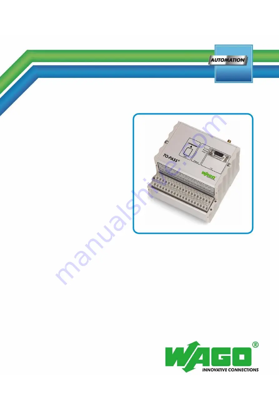
WAGO-TO-PASS® 761
Telecontrol Module Compact, 2 AI
761-111
Telecontrol module for fault detection/indication,
monitoring and remote control
Version 2.0.0
Страница 1: ...Manual WAGO TO PASS 761 Telecontrol Module Compact 2 AI 761 111 Telecontrol module for fault detection indication monitoring and remote control Version 2 0 0 ...
Страница 2: ... 0 571 8 87 5 55 Fax 49 0 571 8 87 85 55 E Mail support wago com Every conceivable measure has been taken to ensure the accuracy and completeness of this documentation However as errors can never be fully excluded we always appreciate any information or suggestions for improving the documentation E Mail documentation wago com We wish to point out that the software and hardware terms as well as the...
Страница 3: ...pen Source GPL 11 2 4 Block Rounding for GPRS Connections 11 2 5 Safety Advice Precautions 12 3 Device Description 15 3 1 Scope of Delivery 15 3 2 Use 15 3 3 View 17 3 4 Connectors 18 3 4 1 Antenna 18 3 4 2 Operating Voltage 19 3 4 3 Grounding 20 3 4 3 1 Framework Assembly 20 3 4 3 2 Insulated Assembly 20 3 4 3 3 Grounding of the TO PASS Telecontrol Module 20 3 4 4 Shielding 21 3 4 4 1 General 21 ...
Страница 4: ...ting Software 42 6 2 Starting the TO PASS Telecontrol Module 43 7 Parameterizing 45 7 1 General Settings 45 7 2 Reading Parameters from the Module 47 7 3 Identity 48 7 4 Addresses 50 7 5 Configuring Inputs and Outputs 53 7 5 1 Digital Inputs 53 7 5 2 Multiplex Input 57 7 5 2 1 Multiplex Settings 58 7 5 2 2 Multiplex Alarm Text 59 7 5 3 Analog Inputs 60 7 5 4 Digital Outputs 62 7 6 Configuring Erro...
Страница 5: ...1 2 Changing the Counter Value or Status 79 8 2 2 Telecontrol with the TO PASS Operator Program 80 8 2 2 1 Inputs Outputs 81 8 2 2 2 Counters 82 8 3 Acknowledging Error Messages 83 8 4 Switching to Standby 84 9 Diagnostics 85 9 1 Test Inputs and Outputs 85 9 2 Testing the Counter Inputs 86 9 3 Testing the Connection 87 9 4 Testing the Modem 88 List of Figures 89 List of Tables 90 ...
Страница 6: ...tions are included if applicable 1 1 Validity of this Documentation This documentation is only applicable to the telecontrol module 761 111 Telecontrol Module Compact 2 AI 1 2 Copyright This Manual including all figures and illustrations is copyright protected Any further use of this Manual by third parties that violate pertinent copyright provisions is prohibited Reproduction translation electron...
Страница 7: ...ates a moderate risk potentially hazardous situation which if not avoided could result in death or serious injury Personal Injury Indicates a low risk potentially hazardous situation which if not avoided may result in minor or moderate injury Damage to Property Indicates a potentially hazardous situation which if not avoided may result in damage to property Damage to Property Caused by Electrostat...
Страница 8: ...s Documentation WAGO TO PASS 761 761 111 Telecontrol Module Compact 2 AI Manual Version 2 0 0 Additional Information Refers to additional information which is not an integral part of this documentation e g the Internet ...
Страница 9: ...ata files are marked in italic type e g C Programme WAGO I O CHECK Menu Menu items are marked in bold letters e g Save A greater than sign between two names means the selection of a menu item from a menu e g File New Input Designation of input or optional fields are marked in bold letters e g Start of measurement range Value Input or selective values are marked in inverted commas e g Enter the val...
Страница 10: ... automation The specialists must be familiar with the current norms and guidelines for the devices and automated environments All changes to the controller should always be carried out by qualified personnel with sufficient skills in PLC programming 2 1 3 Use of the TO PASS Telecontrol Modules in Compliance with Underlying Provisions The TO PASS telecontrol modules receive digital and analog signa...
Страница 11: ...en Source GPL The TO PASS Compact telecontrol module firmware contains Open Source software under GPL According to Section 3b of GPL we offer you the source code You can obtain the source code with licensing terms of the Open Source software from WAGO Kontakttechnik GmbH Co KG on request Send your request to support wago com with the subject Open Source TO PASS Compact 2 4 Block Rounding for GPRS ...
Страница 12: ...lation repair or maintenance work Installation only in appropriate housings cabinets or in electrical operation rooms TO PASS telecontrol modules are exposed operating equipment They may only be assembled in housings cabinets or in electrical operation rooms Access is only permitted via a key or tool to authorized qualified personnel Use SELV PELV power source only The TO PASS telecontrol module m...
Страница 13: ... Only qualified staff can install and maintain the TO PASS remote module and its antenna The transmitted must be off when working on or nearer to the antenna than specified below HF Exposition The external antenna operated with the TO PASS remote module must be at least 20 cm away from people The antenna may not be positioned so that it works in conjunction with any other antenna or transmitter Ho...
Страница 14: ...n an enclosure being resistant to the above mentioned materials Clean tools and materials are imperative for handling devices modules Cleaning only with permitted materials Clean soiled contacts using oil free compressed air or with ethyl alcohol and leather cloths Do not use any contact spray Do not use any contact spray The spray may impair contact area functionality in connection with contamina...
Страница 15: ...mpact module for the connection of signals from plants transmission preparation of values for the operator TO PASS telecontrol modules 761 111 may be used as fault indicator remote data request system telecontrol modules The system is connected in wireless mode to PCs hand computers Internet PCs mobile telephones fax e mail receivers or land line telephones Influences to the system are also possib...
Страница 16: ...sion Standard Extended Extended Parameterizable Time request script Not implemented Not implemented Not implemented Implemented Counter inputs Not supported Not supported Not supported Supported Delay time Not supported Not supported Not supported Supported Turn off time Supported to a limited extent Supported to a limited extent Supported to a limited extent Extended Resolution of analog outputs ...
Страница 17: ...761 111 Telecontrol Module Compact 2 AI Manual Version 2 0 0 3 3 View Figure 1 Front view Position Description 1 SIM Card insert 2 Antenna connection 3 Statusindication 4 PC interface 5 Connecting terminals for the supply inputs and outputs ...
Страница 18: ...ctors 3 4 1 Antenna The screw connector SMA socket for the GSM antenna is located at the top of the housing Figure 2 Antenna connection Observe the maximum length of the antenna cable The total length of the antenna cable shall not exceed 30m The reception quality decreases with increasing antenna cable length ...
Страница 19: ...rce LPS requirements per DIN EN 60950 1 Table 4 Terminal assignment for operating voltage Figure 3 Terminal assignment for operating voltage Connection Short name Designation 1 2 Uv Operating voltage DC 10 30 V 3 4 GND Operating voltage DC 0 V Ground 38 Shield Enclosure screening connection of the PE Connect the shield connection to the DIN rail The shield connection of the TO PASS telecontrol mod...
Страница 20: ...onstructively no direct conduction connection between the cabinet frame or machine parts and the carrier rail Here the earth ground must be set up via an electrical conductor accordingly valid national safety regulations Recommendation The optimal setup is a metallic mounting plate with grounding connection with an electrical conductive link with the carrier rail The separate grounding of the carr...
Страница 21: ... achieve this connect the shield over a large surface area e g WAGO shield connecting system This is especially recommended for large scale systems where equalizing current or high impulse type currents caused by atmospheric discharge may occur Keep data and signal lines away from sources of interference Route data and signal lines separately from all high voltage cables and other sources of high ...
Страница 22: ... WAGO Shield Connecting System The WAGO shield connecting system consists of shield clamping saddles busbars and various mounting carriers to enable a wide variety of setups For more information on this refer to the Accessories section of the main catalog Figure 4 Example of the WAGO shield connecting system ...
Страница 23: ... digital inputs Figure 5 Terminal assignment for digital inputs Connection Short name Designation 5 DI1 Digital input 1 6 DI2 Digital input 2 7 DI3 Digital input 3 8 DI4 Digital input 4 9 Not assigned 10 Not assigned 11 Not assigned 12 Not assigned Digital inputs DI1 DI4 can also be configured alternatively as counter inputs starting from Firmware Version FW 2 33 For more information about configu...
Страница 24: ...inputs Table 7 Counter input pin assignments Figure 6 Counter input pin assignments Connection Short name Explanation 5 DI1 Counter input 1 configurable 6 DI2 Counter input 2 configurable 7 DI3 Counter input 3 configurable 8 DI4 Counter input 4 configurable 38 Shield Shield termination Connect shielding Shielded cables are recommended for the counter inputs When using shielded cables the shield mu...
Страница 25: ...Terminal assignment for analog inputs Figure 7 Terminal assignment for analog inputs Connection Short name Designation 13 AI1 Analog input 1 14 AI1 Analog input 1 15 AI2 Analog input 2 16 AI2 Analog input 2 17 Not assigned 18 Not assigned 19 Not assigned 20 Not assigned 21 Not assigned 22 Not assigned 23 Not assigned 24 Not assigned 25 Not assigned 26 Not assigned 27 Not assigned 28 Not assigned 3...
Страница 26: ... 0 Analog inputs are single ended The analog inputs are single ended and the Aix connections are connected internally to the GND connections Connect shielding Shielded cables are required for analog inputs The cable shield must be connected to the grounded DIN rail see section Connections Shielding ...
Страница 27: ... voltages Only SELV PELV voltages shall be connected to the device terminals Table 9 Terminal assignment for digital outputs Figure 8 Terminal assignment for digital outputs Connection Short name Designation 33 DO1 Digital output 1 34 DO2 Digital output 2 35 DO3 Digital output 3 36 DO4 Digital output 4 37 DO Vcc Voltage for the digital outputs ...
Страница 28: ...Pin Description 1 Not assigned 2 TXD 3 RXD 4 Not assigned 5 GND 6 Not assigned 7 Not assigned 8 Not assigned 9 Not assigned Table 11 PC interface cable assignment WAGO TO PASS PC D Sub 9 Pin Description Pin Description 2 TXD 2 RXD 3 RXD 3 TXD 5 GND 5 GND Connecting laptops and PCs without serial interface If the laptop or PC does not have a serial interface use the USB adapter 761 9005 which is av...
Страница 29: ...m is activated Initialization takes approx 40 s after system start up if everything is OK SMS GPRS processing Antenna is not connected the modem is searching for a network Poor GSM network the modem is searching for a network X Green 1 Hz blinking X Error in communication with SIM card No SIM card available SIM card is defective X Green 5 Hz blinking X Serious error in communication with GSM modem...
Страница 30: ... 14 sol Stripped length 9 mm 10 mm 3 6 2 Supply Table 14 Technical Data Supply Operating voltage 10 V 30 VDC Nominal voltage operation with mains power 24 VDC Nominal voltage operation using battery 12 VDC Bias current with 24 VDC power supply without external protective circuit approx 20 mA Current for transmission with 24 VDC power supply 500 mA 3 6 3 GSM Antenna Connection Table 15 Technical Da...
Страница 31: ...ber of inputs 4 Input type Type 3 acc to IEC 61131 2 Input voltage 0 V 30 V DC Signal voltage 0 0 V 5 V DC Signal voltage 1 7 V 30 V DC Input current max at 30 V DC 2 9 mA 3 6 6 Counter Inputs Table 18 Technical Data Counter Inputs No of counters Max 4 configurable Counter frequency Max 2000 Hz Resolution 32 bits Count direction Up Down 3 6 7 Analog Inputs Table 19 Technical Data Analog Inputs Num...
Страница 32: ...Version 2 0 0 3 6 8 Digital Outputs Table 20 Technical Data Digital Outputs Number of outputs 4 Output type Semiconductor outputs Output current 0 5 A 30 V DC short circuit protected Type of load Resistive inductive lamps Energy dissipation Wmax unique switching off 125 mJ Lmax 2 Wmax I2 ...
Страница 33: ...e per Article 3 2 RoHS Device complies with European RoHS directive FCC Verification per FCC 15b Approval Canada Approval Croatia Approval Mexico Approval Turkey 3 8 Standards and Guidelines 761 111 telecontrol modules meet the following requirements on emission and immunity of interference EMC CE Immunity to interference acc to EN 61000 6 2 2005 and acc to EN 61131 2 2007 EMC CE Emission of inter...
Страница 34: ...n ambient temperature of 20 C to 70 C In the event of higher or lower temperatures proper cooling or heating arrangements must be provided Please contact WAGO Kontakttechnik GmbH Co K G for assistance The TO PASS telecontrol module is designed to mount on a DIN 35 carrier rail 4 1 Mounting the TO PASS telecontrol module to the DIN rail Figure 11 Mounting the TO PASS telecontrol module to the DIN r...
Страница 35: ...ing the TO PASS telecontrol module from the DIN rail Figure 12 Removing the TO PASS telecontrol module from the DIN rail 1 Press the undersurface against the lower DIN rail edge until the TO PASS telecontrol module is no longer locked in place 2 Remove the TO PASS telecontrol module from the DIN rail ...
Страница 36: ...e connection these must be connected in an up circuit wiring assembly for example using WAGO feed through terminals Terminate both solid and ferruled conductors without actuation by simply pushing them in For all other conductor types a suitable operating tool must be used to open the push wire connection for connection Observe strip length When using short ferrules the retention force of the push...
Страница 37: ...ail The shield connection of the TO PASS telecontrol module shield terminal 38 must be connected to the DIN rail The DIN rail must have a low impedance ground see section Connections Ground 5 2 1 Digital Inputs Only connect SELV PELV voltages Only SELV PELV voltages shall be connected to the device terminals Figure 13 Connection example for a switch at DI1 input ...
Страница 38: ...V PELV voltages Only SELV PELV voltages shall be connected to the device terminals Connect shielding Shielded cables are recommended for the counter inputs When using shielded cables the shield must be routed to the grounded DIN rail see Section Connections Shielding Figure 14 Connecting example switching contact at counter input DI1 ...
Страница 39: ...device terminals Analog inputs are single ended The analog inputs are single ended and the Aix connections are connected internally to the GND connections Connect shielding Shielded cables are required for analog inputs The cable shield must be connected to the grounded DIN rail see section Connections Shielding 5 2 3 1 Current Measurement Figure 15 Connection example for a transducer at AI1 input...
Страница 40: ... Voltage measurement cannot be performed via multiplier at the analog inputs since the internal resistance of the TO PASS telecontrol module depends on the input current WAGO 857 Series JUMPFLEX Isolation Amplifiers for level conversion may be used for voltage measurement via TO PASS telecontrol modules Figure 16 Connection example for voltage measurement via U I converter at input AI1 ...
Страница 41: ... 761 111 Telecontrol Module Compact 2 AI Manual Version 2 0 0 5 2 4 Digital Outputs Only connect SELV PELV voltages Only SELV PELV voltages shall be connected to the device terminals Figure 17 Connection example for a relay at DO1 output ...
Страница 42: ...er using a double click 5 Select the CD drive in which you have placed the CD with the operating software 6 Start the WAGO TO PASS_SETUP 2 17 EXE program or a newer version in the main directory on the CD 7 Follow the menu prompting to choose a default installation path Starting with Version 2 17 of the operating software the module files and exported logged information are stored in a central dir...
Страница 43: ...TO PASS telecontrol module it must first be configured with the telephone number 1 Every TO PASS telecontrol module requires an SIM card for proper operation You can obtain an SIM card from any mobile telephone service provider Special data cards are recommended 2 Every SIM card contains a telephone number and a PIN code for enabling the SIM card to be used in the TO PASS telecontrol module Always...
Страница 44: ... PIN button so that the TO PASS telecontrol module does not use the PIN code Also deactivate the PIN on the SIM card To do this insert the SIM card into a cell phone and under menu item Security select Deactivate PIN 11 If the PIN code must be used activate the Use PIN button in the TO PASS operating software and enter the PIN in the field provided Also activate the PIN code for your SIM card usin...
Страница 45: ...og ISDN Select the type of connection for communicating with the TO PASS telecontrol module RS 232 Direct connection via RS 232 cable GSM Dial up using GSM modem on the PC Analog Dial up using analog modem on the PC ISDN Dial up using ISDN modem on the PC Modem init If the connection is to be established via a modem and this modem requires initialization enter the initialization string in this fie...
Страница 46: ... COM1 COMx Here select the serial interface where the communication cable is connected with a RS 232 connection Language English German French Select the langauge for the TO PASS operator interface here To apply the settings and close the dialog window click Save To close the dialog window without applying the settings click Cancel ...
Страница 47: ...u have set the type of connection for communicating with the TO PASS telecontrol module you are then able to read out the parameters of the connected module Select the menu option Edit Read Parameters The software then reads out all the parameters of the TO PASS telecontrol module Then you can adapt the parameter according to your requirements ...
Страница 48: ...to be configured from the project tree under it select the Identity option On the right side you will find the selection field for the function the display field for the name the input field for the telephone number buttons and input fields for the PIN roaming and prepaid and the input field for the alarm counter Figure 19 Configuring the identity ...
Страница 49: ... and enter the PIN number in the field provided Roaming Roaming is always activated in TO PASS telecontrol modules To select a favorite carrier click the Allow button and enter the 5 digit carrier ID in the field provided The telecontrol mode will then always attempt to use this favorite carrier while roaming Prepaid Click the Poll button to transmit information with the data telegram to a prepaid...
Страница 50: ...ges are sent by the TO PASS telecontrol module as SMS however they can also be sent as an e mail fax or voice mail as defined in configuration The TO PASS telecontrol module can also transmit messages to an Internet address Select the TO PASS telecontrol module to be configured from the project tree and the option Addresses The input fields for the addresses are on the right side Figure 20 Configu...
Страница 51: ...il address e g for a T Mobile SIM card 8000 receiver provider net Transmission as fax Follow the instructions from the provider for transmissions as fax messages For T Mobile or Vodafone for example enter the identifier 99 directly in front of the fax number 99057123456789 Number check In this field enter the number of digits to be used for number checking If the entered number is longer than the ...
Страница 52: ...for transmitting the data of the logger APN access In this field enter the APN access point Access Point Name for the SIM card provider e g T Mobile internet t mobile Vodafone web vodafone de The specified APN is not valid for prepaid cards User name In this field enter the user name for SIM card provider access point e g T Mobile Entry required content any Vodafone any Password In this field ente...
Страница 53: ...l Inputs Digital inputs 1 4 can be configured as counter inputs starting from Firmware Version FW 2 33 The counters count up or down from the given starting and end value With upward counting exceeding of two counter values can be reported With downward counting transgression of two counter values can be reported The parameters of the input are given on the right side The buttons and input fields ...
Страница 54: ...ia the visualization system This function is available starting with Firmware Version FW 2 33 Starting value In this field enter the starting value for the counter This field is only active when the input is used as a counter input End value In this field enter the end value for the counter This field is only active when the input is used as a counter input If the starting value is less than the e...
Страница 55: ...applications with GPRS transmission Analog value Use these buttons to select up to four analog values which can also be transmitted with the message when the digital input has been set or when the counted value has violated the first limit Delay time In these fields select the time in hours minutes and seconds by which the message is to be delayed after setting of the digital input If the input is...
Страница 56: ...with GPRS transmission Analog value Use these buttons to select up to four analog values which can also be transmitted with the deactivation message when the digital input has been reset or when the counted value has violated the second limit Delay time In these fields select the time in hours minutes and seconds by which the message is to be delayed after resetting of the digital input If the inp...
Страница 57: ...ollowing applies in this case DI1 20 1 DI2 21 2 DI3 22 4 and DI4 23 8 Thus for example if DI1 and DI3 are set then the binary number is 5 If only DI4 is set then the binary number is 8 In the multiplex table you can define an alarm message for each of the 16 statuses 0 15 The recipients of the messages can be selected using the multiplex settings Counter inputs cannot be evaluated as multiplex inp...
Страница 58: ... Enable Addresses Multiplex operation Click the button Use to enable disable multiplex operation for digital inputs DI1 DI4 If a status combination of digital inputs DI1 DI4 is fulfilled in multiplex operation for which a message text has been defined a corresponding message will then be sent see below Address Use this button to select the addresses to which the message is to be transmitted when t...
Страница 59: ... Multiplex Input entry The input fields for the alarm texts pertaining to the 16 statuses are provided on the right side Figure 24 Configuring multiplex operation alarm texts Table 26 Configuring multiplex operation alarm texts Alarm texts Value 0 Value 15 In these fields enter the texts to be transmitted in the message when the corresponding status combination of digital inputs DI1 DI4 are fulfil...
Страница 60: ...nalog inputs Table 27 Configuring the analog inputs Standardization Input signal Use these buttons to select the input signal for the sensor connected to the TO PASS telecontrol module Min value In this field enter the starting value from which the given value is normalized This value corresponds to the minimum input current value of 0 mA or 4 mA Max value In this field enter the end value up to w...
Страница 61: ...alue Use these buttons to select up to four analog values which can also be transmitted with the message when the analog value has violated the first upper lower limit Second value In this field enter the second limit for which a message is to be sent when this limit is violated upper lower limit see below Use these buttons to select whether the message is to be sent for violation of the upper inc...
Страница 62: ...nnects the DC voltage available at terminal 37 to the corresponding output Deactivation text In this field enter the deactivation text for the output When the TO PASS telecontrol module receives this text as an SMS it deactivates this digital output and disconnects the DC voltage available at terminal 37 Turn off time In these fields select the turn off time for the output in hours minutes and sec...
Страница 63: ...f digital inputs are to be sent as error messages select the desired recipient for the respective input statuses using buttons 1 4 Click the Internet button to also transmit the message to a Web portal In addition you can also specify the analog values that are to be transmitted along with the error message 7 6 2 Limit Messages for Counter Inputs If violations of upper lower counter limits are to ...
Страница 64: ...1 111 Telecontrol Module Compact 2 AI Manual Version 2 0 0 4 Click the Internet button to also transmit the message to a Web portal In addition you can also specify the analog values that are to be transmitted along with the error message ...
Страница 65: ... telecontrol module waits for an acknowledgement after transmitting an alarm SMS Acknowledgement is in the form of an SMS containing the configured response text or a simple call by the recipient to the TO PASS telecontrol module The TO PASS telecontrol module registers the call You then receive an acknowledgement SMS containing the identifier the response text and the alarm text Repetitions In th...
Страница 66: ...ct the TO PASS telecontrol module from the project tree using the identifier Select the entry Repeat times under the option Special Functions The input fields for the Web interval the Web outputs and the SMS interval and buttons for target addresses are located on the right side Figure 28 Configuring the transmission repeat times ...
Страница 67: ...s function is available starting with Firmware Version FW 2 33 Switching input In this field select a digital input to be used for switching of the transmission interval between Web interval Off status of the input and the switching interval On status of the input When the status of the switching input changes the initial transmission is triggered followed by transmission at the cycle time defined...
Страница 68: ... times of day Time adjustment must be performed for limited SMS transmission to check the day of the week and the active time The first SMS is transmitted when the starting value for the active time on an active day is reached The SMS is also transmitted when a cycle time of 0 has been defined The transmission cycle is started when the cycle time is situated within the active time This function is...
Страница 69: ...ent Table 31 Setting the time adjustment Settings Time adjustment The TO PASS telecontrol module sends an SMS to itself and receives the current time from the provider transmitted by this SMS when the SMS button is clicked Time adjustment using an SMS takes place only once when the TO PASS telecontrol module is restarted or when an SMS with the text Time is received When the Internet button is cli...
Страница 70: ...u have adapted all parameters for the TO PASS telecontrol module to your requirements you have to write the parameters to the connected module Select the menu option Edit Write Parameters The software then writes all parameters to the TO PASS telecontrol module After the COM LED goes out the TO PASS telecontrol module is ready for operation ...
Страница 71: ...trol Module Compact 2 AI Manual Version 2 0 0 8 Operation 8 1 Remote Query of Process Values The TO PASS telecontrol module offers two options for remote inquiry of the process values available Query via SMS Query with the TO PASS Operator Program ...
Страница 72: ...99 Alarm counter displays the alarms that are still possible per hour The alarm counter only transmitted when enabled Alarm counter parameter in the Identifier dialog 0 If at least one digital input is configured as a counter input the counter status is added to the SMS The additional lines are added in front of the Status text line The counter status shows the last change that has occurred since ...
Страница 73: ... Explanation 0 Digital input not configured as a counter e ZW Counter is active Counter value d ZW Counter is not active Counter value o ZW Counter overflow Counter vlaue r ZW Counter has been reset Counter value s ZW Counter has been started Counter value c ZW Counter value has been changed Counter value ZW Counter value ...
Страница 74: ...alues with the TO PASS operator program select the menu item Visualization Process values The program establishes a link to the TO PASS telecontrol modules selected Please note the mode used to dial up the TO PASS telecontrol modules either via direct RS 232 cable connection or an analog ISDN or GSM modem dial up The selection is specified in the menu option File Settings ...
Страница 75: ...the on line display is green Figure 30 Visualization of the process values Process values pertaining to inputs are displayed in the upper portion of the window and those pertaining to digital and analog outputs are displayed in the lower portion of the window Digital inputs configured as counter inputs are highlighted in blue Displaying the Analog Values The process values of the analog inputs are...
Страница 76: ...ck the Counter button possible only when inputs have been configured as counters The process values displayed are valid when the on line indicator is highlighted in green Figure 31 Counter process values The counter statuses are shown at the top of the window while the counter values the starting and end values and the limits are shown at the bottom ...
Страница 77: ... AI Manual Version 2 0 0 8 2 Telecontrol TO PASS telecontrol modules offer the option of influencing a process remotely with the help of their analog and digital outputs There are two methods available Telecontrol via SMS Telecontrol with the TO PASS operator program ...
Страница 78: ...S containing the identifier and the transmitted text Example Table 35 Example of parameters for Set DO Parameter Setting Activation text DOUT1 1 Deactivation text DOUT1 0 Turn off time 00 00 00 Send an SMS with the text DOUT1 1 to the TO PASS telecontrol module to switch on output 1 The TO PASS telecontrol module acknowledges the command with an SMS with the identifier and the text DOUT1 1 OK Send...
Страница 79: ...ands for counters Control command Function Cx x 1 4 Select counter 1 4 E Activate counter D Deactivate counter R Reset counter n e g 500 Set counter value Control commands must be concluded with a semicolon The TO PASS telecontrol module acknowledges the command with an SMS containing the identifier and the transmitted text Example To activate Counter 2 and set it to 500 and to also deactivate Cou...
Страница 80: ...es with the TO PASS operator program select the menu item Visualization Process values The program establishes a link to the TO PASS telecontrol modules selected Please note the mode used to dial up the TO PASS telecontrol modules either via direct RS 232 cable connection or an analog ISDN or GSM modem dial up The selection is specified in the menu option File Settings ...
Страница 81: ... Visualization of the process values Process values pertaining to inputs are displayed in the upper portion of the window and those pertaining to digital and analog outputs are displayed in the lower portion of the window Digital inputs configured as counter inputs are highlighted in blue Displaying the Analog Values The process values of the analog inputs are displayed with an 8 bit resolution Yo...
Страница 82: ... in green Figure 33 Counter process values The counter statuses are shown at the top of the window while the counter values the starting and end values and the limits are shown at the bottom To start a counter click the button Activate To stop a counter click the button Deactivate To restore the counter to its starting value click the button Reset To set a counter to a new value enter the required...
Страница 83: ...edgement SMS containing the identifier the response text and the alarm text Acknowledgement by phone call is based on the card being used Some data cards do not allow voice links meaning that acknowledgement is only possible via SMS If the message is not acknowledged within the defined waiting time the TO PASS telecontrol modules sends the error message automatically to the next recipient entered ...
Страница 84: ...y to the respective ready state This takes place with simple changeover via SMS To do this just send an SMS with the text Standby1 to the TO PASS telecontrol modules The TO PASS telecontrol module then transmits all alarm messages to the SMS sender Other receivers defined in the TO PASS telecontrol modules are no longer informed To switch this function off send an SMS with the text Standby0 to the...
Страница 85: ...displayed Figure 34 Test inputs and outputs The process values of the inputs are displayed in the upper area and the process values of the outputs are displayed in the lower area By pressing the buttons Output 1 Output 4 in the upper area switch digital inputs on and off Click OK to end the test and close the window Alternatively the inputs and outputs can also be tested with the help of the menu ...
Страница 86: ...end values and the limits are shown at the bottom To start a counter click the button Activate To stop a counter click the button Deactivate To restore the counter to its starting value click the button Reset To set a counter to a new value enter the required counter value in the corresponding input field and then click the associated button Set to apply the new value Click OK to end the test and ...
Страница 87: ... direct serial link to the TO PASS telecontrol module To test the connection select the menu option Edit Test SMS GPRS The following window is displayed Figure 36 Testing the connection Select the address to send an SMS to and enter the text to be sent Click the Send button to send the message The status of the transmission is then displayed Click OK to end the test and close the window ...
Страница 88: ...k required The modem test may only be performed with a direct serial link to the TO PASS telecontrol module To test the mode select the menu item Modem Test The following window is displayed Figure 37 Testing the modem A link to the modem is established and the signal strength displayed Click OK to end the test and close the window ...
Страница 89: ...ion example for a transducer at AI1 input 39 Figure 16 Connection example for voltage measurement via U I converter at input AI1 40 Figure 17 Connection example for a relay at DO1 output 41 Figure 18 General settings 45 Figure 19 Configuring the identity 48 Figure 20 Configuring the addresses 50 Figure 21 Configuring digital inputs 1 4 53 Figure 22 Configuring digital inputs 5 8 when provided 54 F...
Страница 90: ...nection 30 Table 16 Technical Data GSM Communication 31 Table 17 Technical Data Digital Inputs 31 Table 18 Technical Data Counter Inputs 31 Table 19 Technical Data Analog Inputs 31 Table 20 Technical Data Digital Outputs 32 Table 21 General settings 45 Table 22 Configuring the identity 49 Table 23 Configuring the addresses 51 Table 24 Configuring of digital inputs 54 Table 25 Configuring multiplex...
Страница 91: ...WAGO TO PASS 761 91 761 111 Telecontrol Module Compact 2 AI Manual Version 2 0 0 ...
Страница 92: ...WAGO Kontakttechnik GmbH Co KG Postfach 2880 D 32385 Minden Hansastraße 27 D 32423 Minden Phone 49 5 71 8 87 0 Fax 49 5 71 8 87 1 69 E Mail info wago com Internet http www wago com ...