


WAGO-I/O-SYSTEM 750
Connect Devices
73
750-880, 750-880/025-000 ETHERNET Programmable Fieldbus Controller
Manual
Version 1.0.1
Pos: 64.6 /Serie 750 (WAGO-I/O-SYSTEM)/Anschließen/Leistungskontakte/Feldversorgung - Überschrift 2 @ 7\mod_1266320656354_21.doc @ 50722 @ 2 @ 1
6.2
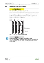
Power Contacts/Field Supply
Pos: 64.7 /Serie 750 (WAGO-I/O-SYSTEM)/Wichtige Erläuterungen/Sicherheitshinweise/Vorsicht/Vorsicht: Verletzungsgefahr durch scharfkantige Messerkontakte! @ 6\mod_1256193279401_21.doc @ 43414 @ @ 1
Risk of injury due to sharp-edged male contacts!
The male contacts are sharp-edged. Handle the module carefully to prevent injury.
Pos: 64.8 /Serie 750 (WAGO-I/O-SYSTEM)/Gerätebeschreibung/Anschlüsse/Leistungskontakte allgemein @ 3\mod_1231828902046_21.doc @ 26017 @ @ 1
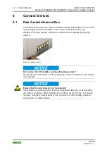
Self-cleaning power jumper contacts used to supply the field side are located on
the right side of both couplers/controllers and some of the I/O modules. These
contacts come as touch-proof spring contacts. As fitting counterparts the I/O
modules have male contacts on the left side.
Figure 35: Example for the arrangement of power contacts
Pos: 64.9 /Serie 750 (WAGO-I/O-SYSTEM)/Wichtige Erläuterungen/Sicherheitshinweise/Hinweis/Hinweis: Feldbusknoten mit smartDESIGNER konfigurieren und überprüfen @ 6\mod_1256193439792_21.doc @ 43420 @ @ 1
Field bus node configuration and test via smartDESIGNER
With the WAGO ProServe
®
Software smartDESIGNER, you can configure the
structure of a field bus node. You can test the configuration via the integrated
accuracy check.
Pos: 64.10 /Dokumentation allgemein/Gliederungselemente/---Seitenwechsel--- @ 3\mod_1221108045078_0.doc @ 21810 @ @ 1


