


WAGO-I/O-SYSTEM 750
I/O Modules 357
750-880, 750-880/025-000 ETHERNET Programmable Fieldbus Controller
Manual
Version 1.0.1
750-634
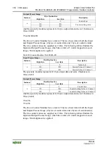
The above Incremental Encoder Interface module has 5 bytes of input data (6
bytes in cycle duration measurement mode) and 3 bytes of output data. The
following tables illustrate the Input and Output Process Image, which has 4 words
mapped into each image. Word alignment is applied.
Table 397: Incremental Encoder Interface Modules 750-634
Input Process Image
Byte Destination
Instance
High Byte
Low Byte
Description
-
S
not used
Status byte
D1 D0 Counter
word
-
(D2) *)
not used
(Periodic time)
n
D4 D3 Latch
word
*)
If cycle duration measurement mode is enabled in the control byte, the cycle duration is
given as a 24-bit value that is stored in D2 together with D3/D4.
The specialty modules represent 1x6 bytes input data and seize 1 Instance in Class
(0x67).
Output Process Image
Byte Destination
Instance
High Byte
Low Byte
Description
-
C
not used
Control byte
D1 D0
Counter
setting
word
- -
n
- -
not used
And the specialty modules represent 1x6 bytes output data and seize 1 Instance in
Class (0x68).
750-637
The above Incremental Encoder Interface Module has a total of 6 bytes of user
data in both the Input and Output Process Image (4 bytes of encoder data and 2
bytes of control/status). The following table illustrates the Input and Output
Process Image, which have 4 words mapped into each image. Word alignment is
applied.
Table 398: Incremental Encoder Interface Modules 750-637
Input and Output Process Image
Byte Destination
Instance
High Byte
Low Byte
Description
-
C0/S0
Control/Status byte of Channel 1
n
D1
D0
Data Value of Channel 1
-
C1/S1
Control/Status byte of Channel 2
n+1
D3
D2
Data Value of Channel 2
The specialty modules represent 2x3 bytes input and output data and seize 2
Instances in Class (0x67) and 2 Instances in Class (0x68).


