


WAGO-I/O-SYSTEM 750
Commissioning 129
750-880, 750-880/025-000 ETHERNET Programmable Fieldbus Controller
Manual
Version 1.0.1
Pos: 80.23.1 /Serie 750 (WAGO-I/O-SYSTEM)/In Betrieb nehmen/Feldbusknoten in Betrieb nehmen/Funktion des Feldbusknotens testen - Überschrift 2 @ 5\mod_1244635054676_21.doc @ 35193 @ 2 @ 1
8.3
Testing the Function of the Fieldbus Node
Pos: 80.23.2 /Serie 750 (WAGO-I/O-SYSTEM)/In Betrieb nehmen/Feldbusknoten in Betrieb nehmen/Hinweis: Weitere Informationen zum Auslesen der IP-Adresse mittels ETHERNET-Settings @ 5\mod_1244637843934_21.doc @ 35196 @ @ 1
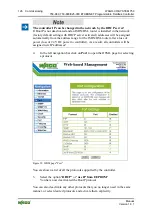
More information about reading the IP address
You can use WAGO-ETHERNET-Settings to read the IP address currently
assigned.
Proceed as described in the section "Assigning IP Address via WAGO-
ETHERNET-Settings."
Pos: 80.23.3 /Serie 750 (WAGO-I/O-SYSTEM)/In Betrieb nehmen/Feldbusknoten in Betrieb nehmen/Feldbusknoten testen, Betriebsspannung ausschalten, Schritt 1 @ 5\mod_1244638193434_21.doc @ 35209 @ @ 1
1.
To ensure that the IP address is correct and to test communication with the
fieldbus node, first turn off the operating voltage of the fieldbus node.
2.
Create a non-serial connection between your client PC and the fieldbus
node.
Pos: 80.23.4 /Serie 750 (WAGO-I/O-SYSTEM)/In Betrieb nehmen/Feldbusknoten in Betrieb nehmen/Hochlauf und LEDs (Controller) @ 4\mod_1243521648173_21.doc @ 34301 @ @ 1
After the power is switched on, the controller is initialized. The fieldbus controller
determines the I/O module configuration and creates a process image. During
startup, the I/O LED (red) will flash. After a brief period, the I/O LED lights up
green, indicating that the fieldbus controller is operational.
Pos: 80.23.5 /Serie 750 (WAGO-I/O-SYSTEM)/In Betrieb nehmen/Feldbusknoten in Betrieb nehmen/Hochlauf und LEDs - Fehler allgemein, Hinweis: Signalisierung/Blinkcode-Ausw. @ 4\mod_1243594306433_21.doc @ 34538 @ @ 1
If an error occurs during start-up indicated by the I/O LED flashing red, evaluate
the error code and argument and resolve the error.
Information
More information about LED signaling
The exact description for evaluating the LED signal displayed is available in the
section "Diagnostics", "LED Signaling".
Pos: 80.23.6 /Serie 750 (WAGO-I/O-SYSTEM)/In Betrieb nehmen/Feldbusknoten in Betrieb nehmen/Feldbusknoten testen, Schritt 3-6 @ 5\mod_1244638753496_21.doc @ 35212 @ @ 1
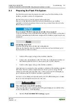
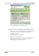
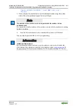
3.
To test the coupler’s newly assigned I/P address, start a DOS window by
clicking on the
Start
menu item
Programs/MS-DOS Prompt
.
4.
In the DOS window, enter the command: "
ping
" followed by the IP address
of your coupler in the following format:
ping
[space]
XXX . XXX . XXX . XXX
(=IP address)
Figure 53: Example for the Function test of a Fieldbus Node
5. When
the
[Enter]
key has been pressed, your PC will receive a query from
the coupler, which will then be displayed in the DOS window.


