62 Configuration and Parameterization
WAGO-I/O-SYSTEM 750
750-658 CAN Gateway
Manual
Version 1.2.1, valid from FW/HW-Version 01/01
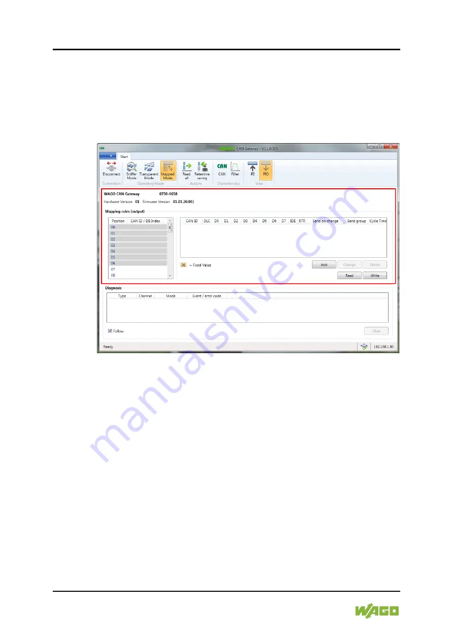
9.1.6.2 "PIO" View
There are two different display windows in the function area:
•
The process image-oriented display (left)
•
The CAN display (right)
These show the current mapping rules for the process image of the output.
Figure 30: Function Area in the "Mapped Mode" – "PIO" View
The following interaction options are available:
•
[Add]
button: Opens the "Add mapping rule" dialog to go to the
configuration dialog. The following interaction options are available in the
dialog itself:
-
CAN ID
input field: The CAN ID of the CAN telegram to map can be
entered here in hexadecimal format.
-
DLC
drop-down list: The user data length of the CAN telegram to be
sent can be selected here (value range 0 … 8). Depending on the
select, corresponding user data input fields appear at the bottom of the
window.
- Input field for data bytes
(D0 … D7)
: The position of the index entered
here describes the position in the process image, whose value is
copied to the respective data byte (D0 … D7).


