22
Device Description
WAGO-I/O-SYSTEM 750 XTR
750-508/040-000 2DO 24 VDC 2A/ Diagn XTR
Manual
Version 1.3.0
3.5
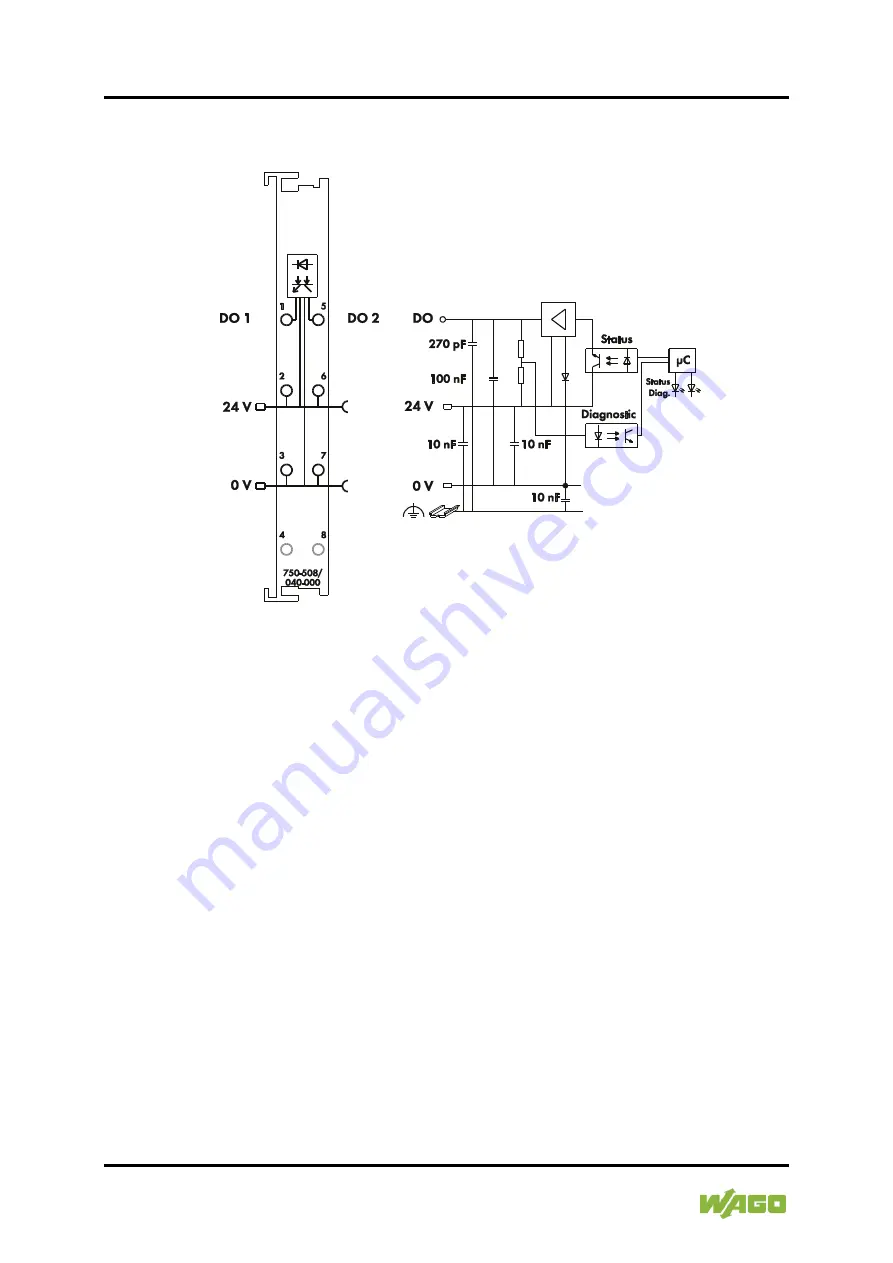
Schematic Diagram
Figure 6: Schematic Diagram
Страница 1: ...Manual WAGO I O SYSTEM 750 XTR 750 508 040 000 2DO 24 VDC 2A Diagn XTR 2 channel digital output 24 VDC 2 0 A diagnostics extreme Version 1 3 0...
Страница 2: ...84 45 55 E Mail support wago com Every conceivable measure has been taken to ensure the accuracy and completeness of this documentation However as errors can never be fully excluded we always apprecia...
Страница 3: ...Packaging 11 2 2 Safety Advice Precautions 12 3 Device Description 15 3 1 View 17 3 2 Connectors 18 3 2 1 Data Contacts Local Bus 18 3 2 2 Power Jumper Contacts Field Supply 19 3 2 3 CAGE CLAMP Connec...
Страница 4: ...Notes 41 8 2 Connection for the I O Module to Safety Switching Devices or F I O Modules 43 8 2 1 General Structure of a Potential Group 43 8 2 2 Examples of Connection 44 9 Use in Hazardous Environmen...
Страница 5: ...in the manual for the used fieldbus coupler controller Consider power layout of the WAGO I O SYSTEM 750 XTR In addition to these operating instructions you will also need the system description Design...
Страница 6: ...dicates a moderate risk potentially hazardous situation which if not avoided could result in death or serious injury Personal Injury Indicates a low risk potentially hazardous situation which if not a...
Страница 7: ...TR Notes about this Documentation 7 750 508 040 000 2DO 24 VDC 2A Diagn XTR Manual Version 1 3 0 Additional Information Refers to additional information which is not an integral part of this documenta...
Страница 8: ...data files are marked in italic type e g C Program Files WAGO Software Menu Menu items are marked in bold letters e g Save A greater than sign between two names means the selection of a menu item from...
Страница 9: ...onments All changes to the coupler or controller should always be carried out by qualified personnel with sufficient skills in PLC programming 2 1 3 Use of the 750 Series in Compliance with Underlying...
Страница 10: ...d by the user The following actions will result in the exclusion of liability on the part of WAGO Kontakttechnik GmbH Co KG Repairs Changes to the hardware or software that are not described in the op...
Страница 11: ...ectrical and electronic equipment can be harmful to the environment and human health 2 1 4 1 2 Packaging Packaging contains materials that can be reused PPWD 94 62 EU and 2004 12 EU packaging guidelin...
Страница 12: ...ion against contact Prevent fire from spreading outside of the enclosure Offer adequate protection against UV irradiation Guarantee mechanical stability Restrict access to authorized personnel and may...
Страница 13: ...e Replace defective or damaged devices Replace defective or damaged device module e g in the event of deformed contacts Protect the components against materials having seeping and insulating propertie...
Страница 14: ...ctrostatic discharge per DIN EN 61340 5 1 3 When handling the devices please ensure that environmental factors personnel work space and packaging are properly grounded Use only direct current DC for i...
Страница 15: ...le can be damaged by the induced voltage produced when inductive loads are de activated An appropriate protection circuit e g a recovery diode must be installed in parallel to the load to limit this i...
Страница 16: ...1 after the fault has been cleared The field voltage and the system voltage are electrically isolated from each other Use in safety related applications When using the I O module please observe the no...
Страница 17: ...343_21 docx 31958 2 1 3 1 View Figure 1 View Table 3 Legend for Figure View Pos Description Details See Section 1 Marking possibility with Mini WSB 2 Status LEDs Device Description Display Elements 3...
Страница 18: ...ch are available as self cleaning gold spring contacts Figure 2 Data Contacts Do not place the I O modules on the gold spring contacts Do not place the I O modules on the gold spring contacts in order...
Страница 19: ...gure 3 Power Jumper Contacts Table 4 Legend for Figure Power Jumper Contacts Contact Type Function 1 Spring contact Potential transmission Uv for field supply 2 Spring contact Potential transmission 0...
Страница 20: ...Figure 4 CAGE CLAMP Connectors Table 5 Legend for Figure CAGE CLAMP Connectors Channel Designation Connector Function 1 DO 1 1 Output DO 1 Signal voltage 24 V 2 Output DO 1 Field supply 24 V 0 V 3 Ou...
Страница 21: ...ignation LED Function 1 Status DO 1 A Status LED of digital output DO 1 Error DO 1 C Error LED of digital output DO 1 2 Status DO 2 E Status LED of digital output DO 2 Error DO 2 G Error LED of digita...
Страница 22: ...22 Device Description WAGO I O SYSTEM 750 XTR 750 508 040 000 2DO 24 VDC 2A Diagn XTR Manual Version 1 3 0 3 5 Schematic Diagram Figure 6 Schematic Diagram...
Страница 23: ...tion system voltage max 14 mA Current consumption power jumper contact typ 24 VDC 7 mA load Voltage supply via power jumper contacts under laboratory conditions for ambient operating temperature 40 C...
Страница 24: ...ort circuit limitation typ PWM See figure below Open circuit detection 0 2 mA Diagnostics Open circuit overload and short circuit Restart after overload Yes Switching rate max 1 kHz Unique switching o...
Страница 25: ...hnical Data Climatic Environmental Conditions Surrounding air temperature operation 40 C 70 C Surrounding air temperature storage 40 C 85 C Relative humidity 95 Elevation above sea level without tempe...
Страница 26: ...d to 750 508 040 000 I O modules Conformity Marking UL508 Korea Certification MSIP REM W43 DOM750 The following Ex approvals have been granted to 750 508 040 000 I O modules CULUS ANSI ISA 12 12 01 Cl...
Страница 27: ...l equipment Equipment requirements in the types of protection EN 60079 7 2015 Electrical equipment in e type of protection with ec level of protection EN 60079 15 2010 Electrical equipment in the n ty...
Страница 28: ...shocks per axis and direction half sine EN 50155 EN 61373 Random vibration Category 1 classes A and B Shock 5g 30 ms Category 1 classes A and B Environmental Requirements EN 61850 3 Achieved EN 60721...
Страница 29: ...C37 90 1 4 kV Surge Voltage Surge EN 61000 4 5 EN 60255 26 1 kV conductor conductor 2 kV conductor ground Conducted Disturbances Induced by High frequency Fields EN 61000 4 6 EN 60255 26 10 V 150 kHz...
Страница 30: ...ons EN 61000 4 17 EN 60255 26 15 Damped Oscillatory Waves EN 61000 4 18 EN 60255 26 IEEE C37 90 1 1 25 kV conductor conductor 2 5 kV conductor ground Voltage Dips Short term Interruptions and Voltage...
Страница 31: ...GHz 60 dB V m AV 3 GHz 6 GHz Shipbuilding Class B 80 dB V m 50 dB V m QP 150 kHz 300 kHz 50 dB V m 34 dB V m QP 0 3 MHz 30 MHz 54 dB V m QP 30 MHz 2 GHz 24 dB V m QP 156 MHz 165 MHz Shipbuilding Clas...
Страница 32: ...EMC A or EMC B Table 20 Standards and Rated Conditions for Rail Applications EN 50155 Class Standard Compliance 4 1 Rated Operating Conditions 4 1 1 Altitude above sea level AX EN 50125 1 4 1 2 Ambien...
Страница 33: ...he process image of the corresponding coupler controller Table 21 Output Bits Bit 1 Bit 0 DO 2 DO 1 DO 1 Signal state DO 1 Digital output channel 1 DO 2 Signal state DO 2 Digital output channel 2 Tabl...
Страница 34: ...are sharp edged Handle the I O module carefully to prevent injury Do not touch the blade contacts Insert I O modules only from the proper direction All I O modules feature grooves for power jumper con...
Страница 35: ...when devices are energized High voltage can cause electric shock or burns Switch off all power to the device prior to performing any installation repair or maintenance work Temperature range applies...
Страница 36: ...ule snapped in place the electrical connections for the data contacts and power jumper contacts if any to the fieldbus coupler controller or to the previous or possibly subsequent I O module are estab...
Страница 37: ...each CAGE CLAMP Do not connect more than one conductor at one single connection If more than one conductor must be routed to one connection these must be connected in an up circuit wiring assembly fo...
Страница 38: ...es WAGO I O SYSTEM 750 XTR 750 508 040 000 2DO 24 VDC 2A Diagn XTR Manual Version 1 3 0 6 2 Connection Examples 6 2 1 2 wire Connection Figure 12 2 wire Connection 6 2 2 3 wire Connection Figure 13 3...
Страница 39: ...rt circuit at output to ground Off Red No load connected to the output Short circuit at output to 24 V Overtemperature on overload The diagnostics can only be fully interpreted by analyzing the displa...
Страница 40: ...image see Section Process Image provides information on cases of error Bit 0 of the input bits contains diagnostic information for output DO 1 bit 1 contains diagnostic information for output DO 2 It...
Страница 41: ...1 Important Notes Only operate interference free I O modules at a safe extra low voltage When using interference free I O modules only use power supplies with protective extra low voltage PELV SELV fo...
Страница 42: ...switching device Reverse supply must absolutely be avoided Avoid short circuits between outputs Short circuits between outputs of different interference free digital output modules must absolutely be...
Страница 43: ...filter modules Table 25 Supply or Filter Modules for Setting up a Potential Group Supply Terminal Blocks 750 602 040 000 750 612 040 000 750 613 040 000 Field side power supply filter Power supply fil...
Страница 44: ...lications WAGO I O SYSTEM 750 XTR 750 508 040 000 2DO 24 VDC 2A Diagn XTR Manual Version 1 3 0 8 2 2 Examples of Connection Two Channel Single Pole Power Supply Disconnection Figure 15 Two Channel Sin...
Страница 45: ...750 XTR Using in Safety Related Applications 45 750 508 040 000 2DO 24 VDC 2A Diagn XTR Manual Version 1 3 0 Two Channel Double Pole Power Supply Disconnection Figure 16 Two Channel Double Pole Discon...
Страница 46: ...zardous areas and shall be used in accordance with the marking and installation regulations The following sections include both the general identification of components devices and the installation re...
Страница 47: ...8 040 000 2DO 24 VDC 2A Diagn XTR Manual Version 1 3 0 9 1 Marking Configuration Examples 9 1 1 Marking for Europe According to ATEX and IECEx Figure 17 Marking Example According to ATEX and IECEx Fig...
Страница 48: ...xplosion group of dust T135 C Max surface temperature of the enclosure without a dust layer Dc Equipment protection level EPL Mining I Equipment group Mining M2 Category High level of protection Ex Ex...
Страница 49: ...ments 49 750 508 040 000 2DO 24 VDC 2A Diagn XTR Manual Version 1 3 0 Figure 19 Marking Example for Approved Ex i I O Module According to ATEX and IECEx Figure 20 Text Detail Marking Example for Appro...
Страница 50: ...t layer Dc Equipment protection level EPL Mining I Equipment Group Mining M2 M1 Category High level of protection with electrical circuits which present a very high level of protection Ex Explosion pr...
Страница 51: ...tes of America NEC and Canada CEC Figure 21 Marking Example According to NEC Figure 22 Text Detail Marking Example According to NEC 500 Table 28 Description of Marking Example According to NEC 500 Mar...
Страница 52: ...protection level EPL Associated apparatus with intrinsic safety circuits for use in Zone 20 IIC Group T4 Temperature class Gc Equipment protection level EPL Figure 24 Text Detail Marking Example for...
Страница 53: ...nA Type of protection ia IIIC Type of protection and equipment protection level EPL Associated apparatus with intrinsic safety circuits for use in Zone 20 IIC Group T4 Temperature class Gc Equipment...
Страница 54: ...when replacing components The product is an open system As such the product must only be installed in appropriate enclosures or electrical operation rooms to which the following applies Can only be o...
Страница 55: ...particular Operating DIP switches coding switches or potentiometers Replacing fuses Wiring connecting or disconnecting of non intrinsically safe circuits is only permitted in the following cases The c...
Страница 56: ...phone networks or telecommunication cables WARNING The radio receiver module 750 642 may only be used to connect to external antenna 758 910 WARNING Product components with fuses must not be fitted in...
Страница 57: ...3 Figure 15 Two Channel Single Pole Disconnection Example 44 Figure 16 Two Channel Double Pole Disconnection Example 45 Figure 17 Marking Example According to ATEX and IECEx 47 Figure 18 Text Detail M...
Страница 58: ...ications 27 Table 17 Climatic and Mechanical Environmental Conditions and Shipbuilding 28 Table 18 EMC Immunity to Interference 29 Table 19 EMC Emission of Interference 31 Table 20 Standards and Rated...
Страница 59: ...WAGO I O SYSTEM 750 XTR List of Tables 59 750 508 040 000 2DO 24 VDC 2A Diagn XTR Manual Version 1 3 0...
Страница 60: ...WAGO Kontakttechnik GmbH Co KG Postfach 2880 D 32385 Minden Hansastra e 27 D 32423 Minden Phone 49 571 887 0 Fax 49 571 887 844169 E Mail info wago com Internet www wago com...