EN
3.
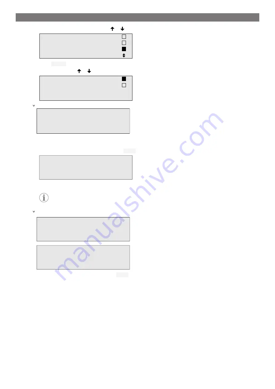
In the basic menu use the cursor keys or to select
Other selections
.
Short selection
Free selection
Other selections
ENTER-OK
4.
Press
ENTER
to confirm.
5.
Use the cursor keys or to select
A/C system test
.
A/C system test
Service.
ENTER-OK STOP-EXIT
A prompt appears asking you to check the air conditioning system:
Check the A/C system
STOP-EXIT
6.
Check the high and low pressure of the air conditioning system in accordance with the manufacturer's specifi-
cations.
7.
To end the air conditioning system test, press
STOP
.
ENTER-OK
the A/C system
service hose from
Disconnect the HP
8.
Close the HP quick connector and detach it from the air conditioning system.
Note
If you have turned off the vehicle engine to uncouple the HP quick connector, restart the engine
and turn on the air conditioning.
The following display messages appear:
service hoses!
Recovery from the
Wait!
STOP-EXIT
Process completed
9.
To end the air conditioning test, press the
STOP
button.
13.8 Free Selection
The
Free selection
menu is used to perform air conditioning maintenance step-by-step. You can perform the
same processes as in the short selection menu, but also omit individual procedures. In addition, it is possible to
enter the values for each individual process using the keypad. You can also enter the vehicle data for the service
report in this menu.
The following four processes can be performed individually in the
Free selection
menu:
•
Recycling phase: Extraction, recycling of the refrigerant, pressure rise test, draining the waste oil.
•
Vacuum phase: Evacuating the system, leak test / vacuum check.
•
Filling phase: Before working on the vehicle air conditioner, a leak inspection must be carried out. The air con-
ditioner is filled with a sample of refrigerant. The pressure in the air conditioner must remain constant over a
period of 5
min. The air conditioner can only be completely filled if this test has been successfully completed.
24
Содержание 9103303105
Страница 9: ...EN 16 USB port 9 ...
Страница 41: ...EN 17 1 Flowchart ASC6300 G Legend 41 ...
Страница 44: ...EN 17 2 Flowchart ASC6400 G Legend 44 ...
Страница 47: ...EN 17 3 Circuit diagram ASC6300 G 47 ...
Страница 48: ...EN 48 ...
Страница 49: ...EN 17 4 Circuit diagram ASC6400 G 49 ...
Страница 50: ...EN 50 ...
Страница 58: ...FR 16 Port USB 58 ...
Страница 92: ...FR 17 1 Organigramme ASC6300 G Légende 92 ...
Страница 95: ...FR 17 2 Organigramme ASC6400 G Légende 95 ...
Страница 98: ...FR 17 3 Schéma électrique ASC6300 G 98 ...
Страница 99: ...FR 99 ...
Страница 100: ...FR 17 4 Schéma électrique ASC6400 G 100 ...
Страница 101: ...FR 101 ...
Страница 109: ...DE 16 USB Anschluss 109 ...
Страница 142: ...DE 17 1 Flussdiagramm ASC6300 G Legende 142 ...
Страница 145: ...DE 17 2 Flussdiagramm ASC6400 G Legende 145 ...
Страница 148: ...DE 17 3 Schaltplan ASC6300 G 148 ...
Страница 149: ...DE 149 ...
Страница 150: ...DE 17 4 Schaltplan ASC6400 G 150 ...
Страница 151: ...DE 151 ...
Страница 159: ...RU 16 USB порт 159 ...
Страница 192: ...RU 17 1 Блок схема ASC6300 G Пояснения 192 ...
Страница 195: ...RU 17 2 Блок схема ASC6400 G Пояснения 195 ...
Страница 198: ...RU 17 3 Схема соединений ASC6300 G 198 ...
Страница 199: ...RU 199 ...
Страница 200: ...RU 17 4 Схема соединений ASC6400 G 200 ...
Страница 201: ...RU 201 ...
Страница 209: ...ES 16 Conexión USB 209 ...
Страница 244: ...ES 17 1 Diagrama de flujo ASC6300 G Leyenda 244 ...
Страница 247: ...ES 17 2 Diagrama de flujo ASC6400 G Leyenda 247 ...
Страница 250: ...ES 17 3 Esquema de conexiones ASC6300 G 250 ...
Страница 251: ...ES 251 ...
Страница 252: ...ES 17 4 Esquema de conexiones ASC6400 G 252 ...
Страница 253: ...ES 253 ...
Страница 254: ...4445103554 2022 11 30 ...


