background image

CT Repair

Spider

wc_tx000553gb.fm

79

7.2

Spider Assembly—Components


Ref.

Description

Ref.

Description

8

Spider

47

Cotter pin

9

Blade lift ring

55

Hex head screw

10

Bearing holder

57

Hex head screw

11

Tube

59

Lifting bolt

12

Yoke

61

Setscrew

13

Link

62

Screw

14

Eccentric adjuster

64

Screw

27

Bearing sleeve

65

Plug (threaded)

28

Ball bearing

67

Fender washer

40

Cap plug

72

Washer

41

Grease fitting

88

Retaining ring

43

Clevis pin

94

Set-combo blade

44

Grease fitting

95

Blade arm assembly

45

Cotter pin

Содержание CT 36

Страница 1: ...www wackergroup com Walk Behind Trowels CT 36 CT 48 REPAIR MANUAL 0163091en 003 1007 0 1 6 3 0 9 1 E N...

Страница 2: ......

Страница 3: ...happening in the future This manual provides information and procedures to safely repair and maintain the above Wacker model s For your own safety and protection from injury carefully read understand...

Страница 4: ...ment please contact Wacker Corporation The information contained in this manual was based on machines in production at the time of publication Wacker Corporation reserves the right to change any porti...

Страница 5: ...2 1 Dimensions and Weight 18 2 2 Engine 20 2 3 Trowel 24 2 4 Sound and Vibration Data 25 3 Operation 26 3 1 Application 26 3 2 New Machine Set up 26 3 3 Recommended Fuel 26 3 4 Installing Blades 27 3...

Страница 6: ...onal Weights 51 4 15 Lifting 52 4 16 Storage 54 4 17 Troubleshooting 55 5 Guide Handle 56 5 1 Replacing the Throttle Cable 56 5 2 Adjusting the Throttle Lever 58 5 3 Upper Handle Twist Pitch Control E...

Страница 7: ...ing the Spider 88 7 8 Rebuilding the Lift Ring Assembly 90 8 Drivetrain 92 8 1 Drivetrain Exploded View 92 8 2 Drivetrain Components 93 8 3 Engine Removal 94 8 4 Engine Installation 96 8 5 Engine Wiri...

Страница 8: ...us situation which if not avoided could result in minor or moderate injury NOTICE Used without the safety alert symbol NOTICE indicates a hazardous situation which if not avoided could result in prope...

Страница 9: ...ve machine running unattended 1 2 5 NEVER operate the machine with the beltguard missing Exposed drive belt and pulleys create potentially dangerous hazards that can cause serious injuries 1 2 6 NEVER...

Страница 10: ...nd follow the warning instructions in the engine owner s manual and the safety guidelines below Failure to follow the warnings and safety guidelines could result in severe injury or death 1 3 1 DO NOT...

Страница 11: ...f fuels or flammable solvents to clean parts especially in enclosed areas Fumes from fuels and solvents can become explosive 1 4 5 DO NOT remove blades while the machine is hanging overhead 1 4 6 ALWA...

Страница 12: ...Safety Information CT 36 CT 48 wc_si000139gb fm 12 1 5 Label Locations...

Страница 13: ...ER Engines emit carbon monoxide operate only in well ventilated area Read the Operator s Manual No sparks flames or burning objects near the machine Shut off the engine before refueling WARNING Hot su...

Страница 14: ...n i s h i t G l e i t s c h e i b e v o m B e t o n g l t t e r e n t f e r n e n b e v o r d a s G e r t u b e r K o p f h h e g e h o b e n w i r d G l e i t s c h e i b e k a n n f a l l e n u n d...

Страница 15: ...infor mation found on this plate so it will be available should the nameplate become lost or dam aged When ordering parts or requesting ser vice information you will always be asked to specify the mo...

Страница 16: ...formation CT 36 CT 48 wc_si000139gb fm 16 Label Meaning Open the fuel flow valve Close the choke Turn engine key switch to ON position Place throttle in the IDLE position Pull the rewind starter Open...

Страница 17: ...CT 36 CT 48 Safety Information wc_si000139gb fm 17 Press the stop button Turn engine key switch to OFF position Close the fuel flow valve Label Meaning...

Страница 18: ...e A Variable Speed V Engine Horse Power 4 5 6 8 9 11 13 Handle Type Item No L mm in Pitch Type Weight kg lbs Solid 0159659 1740 68 5 Twist 10 21 Folding 0159660 1740 68 5 Twist 12 26 5 Adjustable Fold...

Страница 19: ...x36x41 94 208 103 226 CT 36 8A V 0009442 915x915x686 36x36x27 2005x915x1040 79x36x41 94 208 103 226 CT 36 9 0009444 915x915x686 36x36x27 2005x915x1040 79x36x41 90 199 98 217 CT 36 9 V 0009447 915x915x...

Страница 20: ...031 0 6 0 7 0 024 0 028 Engine Speed full load rpm 3800 100 Engine Speed idle rpm 1450 100 1400 100 Clutch engagement rpm 1800 Valve Clearance cold intake exhaust mm in 0 15 0 006 0 20 0 008 0 07 0 1...

Страница 21: ...0 7 0 8 0 028 0 031 Engine Speed full load rpm 3800 100 Engine Speed idle rpm 1450 100 1400 100 Clutch engagement rpm 1800 Valve Clearance cold intake exhaust mm in 0 15 0 006 0 20 0 008 0 07 0 13 0...

Страница 22: ...031 Engine Speed full load rpm 3800 100 Engine Speed idle rpm 1450 100 1400 100 Clutch engagement rpm 1800 Valve Clearance cold intake exhaust mm in 0 15 0 006 0 20 0 008 0 07 0 13 0 0028 0 0051 0 17...

Страница 23: ...Electrode Gap mm in 0 7 0 8 0 028 0 031 Engine Speed full load rpm 3800 100 Engine Speed idle rpm 1450 100 Clutch engagement rpm 1800 Valve Clearance cold intake exhaust mm in 0 15 0 006 0 20 0 008 A...

Страница 24: ...eter mm in Number of Blades Gear Box Lubrication type ml oz Speed Range rpm Pitch Range degrees Trowel CT 36 5A 0009438 0620106 915 36 4 Mobil Glygoyle 460 Approx 620 21 60 125 0 30 CT 36 6 0009443 CT...

Страница 25: ...d pressure level LpA at the operator s location The weighted effective acceleration value determined according to ISO 8662 Part 1 is C m s2 The sound and vibration specifications were obtained with th...

Страница 26: ...depend on operator skill and job conditions DO NOT use this machine for any application other than troweling concrete 3 2 New Machine Set up Trowels are shipped from the factory with the handle remove...

Страница 27: ...r pans and finish blades Note Trowel blades must NOT be interchanged i e do NOT put larger diameter blades on a smaller diameter trowel 3 4 1 Finish blades are flat on both edges and can be installed...

Страница 28: ...the way forward away from the operator OR turn the twist pitch control handle counterclockwise as far as possible Connect the cable to the fork k as shown and adjust the cable nut m so the cable is sn...

Страница 29: ...CT 36 CT 48 Operation wc_tx000373gb fm 29 wc_gr001758 e f g h j k...

Страница 30: ...fm 30 3 6 Controls See Graphic wc_gr003219 Ref Description Ref Description a Throttle lever d Handle height adjustment if equipped b Stop button e Foldable handle adjustment if equipped c Twist pitch...

Страница 31: ...r loses his her grip on the trowel the engine control module will sense that the machine is spinning and shut off the engine The momentum of the spinning trowel will engage the brake and stop the hand...

Страница 32: ...is started when the throttle is not in the idle position the engine should not start This is a feature of the engine control module that prevents wide open throttle startup 3 9 4 Pull starter rope j D...

Страница 33: ...raphic wc_gr003219 wc_gr001098 3 10 1 Reduce engine RPM to idle by moving the throttle lever to idle position a1 3 10 2 Push the stop button b 3 10 3 Turn engine switch to OFF h2 3 10 4 Close fuel val...

Страница 34: ...tarted when the throttle is not in the idle position the engine should not start This is a feature of the engine control module that prevents wide open throttle startup 3 11 4 Pull starter rope j Do n...

Страница 35: ...op Wacker See Graphic wc_gr003219 wc_gr002747 3 12 1 Reduce engine RPM to idle by moving the throttle lever to idle position a1 3 12 2 Push the stop button b 3 12 3 Turn engine switch to OFF h1 3 12 4...

Страница 36: ...or not functioning properly 3 14 Operation See Graphic wc_gr003239 ALWAYS test the function of the engine control module before operating the trowel DO NOT operate the trowel if the engine control mo...

Страница 37: ...ch set of work passes be at 90 to the previous set of work passes This will help prevent the creation of valleys in the slab surface For example in the illustration the second set of work passes 2 is...

Страница 38: ...sed when the input shaft is rotated and is shifted out from its seated position This is accomplished when the gear on this shaft rotates working against the output shaft gear forcing the shaft out If...

Страница 39: ...operator to decrease pitch For final finishing stages it is sometimes desirable to add weights to the trowel guard rings to increase the burnishing force Wacker supplies weight kits for this purpose R...

Страница 40: ...n on engine maintenance Daily After first 20 hrs Every 50 hrs Every 100 hrs Every 300 hrs Check fuel level Check engine oil level Inspect fuel lines Inspect air filter Replace as needed Check external...

Страница 41: ...l devices and systems may be performed by any repair establishment or individual Daily After first 20 hours Every 2 weeks or 50 hrs Every month or 100 hrs Every year or 300 hrs Every 500 hrs Check fue...

Страница 42: ...e interests of environmental protection place a plastic sheet and a container under the machine to collect any liquid which drains off Dispose of this liquid in accordance with environmental protectio...

Страница 43: ...id which drains off Dispose of this liquid in accordance with environmental protection legislation 4 4 2 Remove the oil drain cap a 4 4 3 Allow the oil to drain 4 4 4 Install the drain cap 4 4 5 Fill...

Страница 44: ...low flash point solvents for cleaning the air cleaner A fire or explosion could result To service 4 5 1 Remove air cleaner cover a Remove both elements and inspect them for holes or tears Replace dama...

Страница 45: ...ry and dusty conditions the elements should be maintained daily Replace an element when saturated with dirt that cannot be removed 4 6 1 Remove the air cleaner cover a Remove the filter assembly by pu...

Страница 46: ...ing the engine Do not touch the muffler while it is hot Note Refer to the Technical Data for the recommended spark plug type and the electrode gap setting 4 7 1 Remove the spark plug and inspect it 4...

Страница 47: ...le solvent Dry and reinstall them 4 8 4 Turn the fuel valve on and check for leaks 4 9 Cleaning Fuel Strainer Wacker See Graphic wc_gr001093 4 9 1 To remove water and dirt close the fuel lever and rem...

Страница 48: ...he blades will engage unless the belt is removed from the machine Adjust engine to the no load or idle speed per the Technical Data 4 10 1 Start the engine and allow it to warm up to normal operating...

Страница 49: ...ill engage unless the belt is removed from the machine The pilot screw a is fitted with a limiter cap to prevent excessive enrichment of the air fuel mixture in order to comply with emission regulatio...

Страница 50: ...ng To replace the drive belt 4 12 1 Disconnect the spark plug lead To avoid accidental starting of the engine always disconnect the spark plug lead before working on machine 4 12 2 Loosen the screws d...

Страница 51: ...ck quantity through plug a located on side of gearbox Oil level should be to bottom of the plug threads See Technical Data for oil quantity and type 4 14 Optional Weights To install optional weights p...

Страница 52: ...et The lumber must be long enough to extend past the ring guard c Balance the weight between the partners and lift the machine by the handle and the lumber To reduce risk of back injury while lifting...

Страница 53: ...CT 36 CT 48 Maintenance wc_tx000374gb fm 53...

Страница 54: ...ove spark plug and pour 15 ml ounce of SAE 30 engine oil into the cylinder Replace spark plug and crank engine to distribute oil Refer to engine manual Clean dirt from cylinder cylinder head fins blow...

Страница 55: ...throttle lever and cable for proper operation Engine runs poor trowel operation Check drive belt for wear or damage Check clutch for wear or damage Clean debris from moving parts and trowel arms Engin...

Страница 56: ...and the casing fastener from the throttle control lever b and remove the throttle cable from the machine Assembly 5 1 6 Place the engine s throttle control lever in the idle position Connect the thro...

Страница 57: ...CT Repair Guide Handle wc_tx000551gb fm 57 wc_gr003362 Honda Honda Wacker d a c b f e g f e g f e g...

Страница 58: ...so that the engine s throttle control can reach the idle slow position 5 2 2 Remove the screw a on top of throttle lever b and lift off the throttle lever 5 2 3 Position the throttle lever in the idl...

Страница 59: ...CT Repair Guide Handle wc_tx000551gb fm 59 wc_gr003361 1 2 a e d c b...

Страница 60: ...Guide Handle CT Repair wc_tx000551gb fm 60 5 3 Upper Handle Twist Pitch Control Exploded View...

Страница 61: ...n 1 Handle 13 Pin 3 Push button switch 14 Retaining ring 4 Nut 15 Spring 5 Bearing holder 16 Ball 6 Wiring harness 17 Tie cable 7 Cable 18 Hex head screw 8 Throttle cable 19 Hex head screw 9 Kit CT th...

Страница 62: ...hread the pitch control cable through the upper handle Attach the pitch control device i twist pitch or Pro Shift to the upper handle On models with twist pitch control turn the knob counterclockwise...

Страница 63: ...CT Repair Guide Handle wc_tx000551gb fm 63 wc_gr003360 a d f b h g c d e...

Страница 64: ...ttach the knob f to the twist control assembly c 5 6 6 Place the pitch control cable d into the twist control assembly and secure it with the roll pin e 5 6 7 Lubricate the threads g on the twist cont...

Страница 65: ...CT Repair Guide Handle wc_tx000551gb fm 65 wc_gr003363 g a d e b f c...

Страница 66: ...s 60 5 7 3 Pull the lower handle 17 from the gearbox 5 7 4 If replacing the pulley 25 pull the cotter pin 46 from the clevis pin 42 and remove the pulley Assembly 5 7 5 If removed replace the pulley 2...

Страница 67: ...the stop screw a carry out the following procedures Removal 5 8 1 Remove the protective boot b 5 8 2 Disconnect the wire c 5 8 3 Unthread the stop switch from the handle Installation 5 8 4 Thread the...

Страница 68: ...Guide Handle CT Repair wc_tx000551gb fm 68 Notes...

Страница 69: ...nge the belt is the same for both clutches To replace the drive belt 6 1 1 Disconnect the spark plug lead To avoid accidental starting of the engine disconnect the spark plug lead before working on th...

Страница 70: ...Clutch Ref Description Ref Description 3 Beltguard 53 Hex head screw 4 Beltguard plate 54 Hex head screw 23 Clutch assembly 69 Fender washer 24 Pulley 70 Flat steel washer 26 V belt 72 Washer 36 Space...

Страница 71: ...tion Ref Description 3 Upper belt guard 58 Hex head screw 4 Beltguard plate 69 Fender washer 23 Clutch 70 Washer 24 Clutch pulley 71 Washer 26 Belt 84 Key 36 Spacer 127 Lower beltguard 51 Screw 132 Ke...

Страница 72: ...crankshaft Push against the bolt head rather than directly against the threads of the crankshaft 6 4 4 Remove the spacer 36 and the key 84 from the crankshaft Inspect the key and the keyways for sign...

Страница 73: ...52gb fm 73 6 5 Standard Clutch Exploded View Ref Description Ref Description 1 Clutch assembly incl 2 8 5 Clutch shoe 2 Setscrew 6 Ball bearing 3 Clutch plate 7 Clutch drum 4 Spring 8 Clutch pulley wc...

Страница 74: ...e torch Then while protecting your hands from any hot surface pick up the clutch pulley bearing assembly a and strike it against a wooden or similar surface b The force of the blow should free the bea...

Страница 75: ...CT Repair Clutch wc_tx000552gb fm 75 wc_gr003364 a b wc_gr002068 2 3 4 5 7 6 8 1...

Страница 76: ...move the bolt 58 that secures the clutch pulley 24 to the gearbox input shaft and remove the clutch pulley 6 7 5 Remove the key 132 Installation 6 7 6 Install the key 132 onto the gearbox input shaft...

Страница 77: ...CT Repair Clutch wc_tx000552gb fm 77 81 4 50 23 84 74 51 3 36 71 24 132 26 70 58 69 53 127 wc_gr003383...

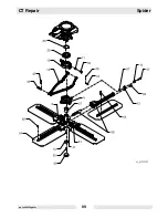
Страница 78: ...Spider CT Repair wc_tx000553gb fm 78 7 Spider 7 1 Spider Assembly Exploded View...

Страница 79: ...ad screw 10 Bearing holder 57 Hex head screw 11 Tube 59 Lifting bolt 12 Yoke 61 Setscrew 13 Link 62 Screw 14 Eccentric adjuster 64 Screw 27 Bearing sleeve 65 Plug threaded 28 Ball bearing 67 Fender wa...

Страница 80: ...ly starting the engine when turning the trowel blades 7 3 1 Pitch the blades so that they lie flat 7 3 2 Remove the screws a that secure the blade b to the blade arm and remove the blade Do so for all...

Страница 81: ...CT Repair Spider wc_tx000553gb fm 81 wc_gr003365 a b...

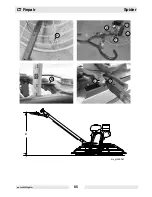
Страница 82: ...ding outside of the spider 7 4 5 Inspect the arm for straightness Use the flattest and smoothest surface available and two spacers h of equal size Place the spacers on the surface Set the arm on the s...

Страница 83: ...CT Repair Spider wc_tx000553gb fm 83 wc_gr003356 a b c e d x x x x x x 180 g f i h...

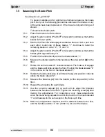
Страница 84: ...above the blade labeled 1 7 5 6 Measure the distance x from the handle at the stop switch b to the floor 7 5 7 Rotate the entire trowel 90 counterclockwise The brake will engage and the blades will s...

Страница 85: ...CT Repair Spider wc_tx000553gb fm 85 wc_gr003357 x a c d b 1 2 3 4...

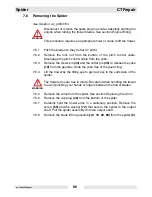
Страница 86: ...5 to release the yoke 12 from the gearbox Slide the yoke free of the guard ring 7 6 4 Lift the trowel by the lifting eye to gain access to the underside of the spider The trowel arms are free to rotat...

Страница 87: ...CT Repair Spider wc_tx000553gb fm 87...

Страница 88: ...the blade lift ring over the spider 7 7 5 Apply Loctite 243 or equivalent to the screw 55 use the screw and the washer 72 to secure the spider to the output shaft Torque the screw to 25 Nm 18 ft lbs 7...

Страница 89: ...CT Repair Spider wc_tx000553gb fm 89...

Страница 90: ...ompound that secures it to the bearing holder 9 Assembly 7 8 6 Lubricate the bearing sleeve 27 with a thin film of grease and press it into the blade lift ring 9 7 8 7 Lubricate the ball bearing 28 wi...

Страница 91: ...CT Repair Spider wc_tx000553gb fm 91 wc_gr003358 88 28 28 10 10 11 59 9 9 27 27...

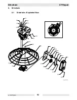
Страница 92: ...Drivetrain CT Repair wc_tx000554gb fm 92 8 Drivetrain 8 1 Drivetrain Exploded View a...

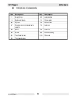
Страница 93: ...s Ref Description Ref Description 1 Guard ring 68 Lockwasher 4 Beltguard plate 73 Flat washer 36 Spacer 76 Flat washer 37 Engine control module gyro switch 78 Locknut 49 Stud 79 Locknut 50 Screw 98 Oi...

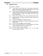
Страница 94: ...ol module gyro switch See section Engine Wiring 8 3 3 Remove the drive belt as described in section Replacing the Drive Belt 8 3 4 Remove the clutch assembly as described in section Replacing the Stan...

Страница 95: ...CT Repair Drivetrain wc_tx000554gb fm 95 a...

Страница 96: ...drive shaft and slide on the spacer 36 8 4 5 Reinstall the clutch assembly as described in section Replacing the Clutch 8 4 6 Reinstall the drive belt as described in section Replacing the Drive Belt...

Страница 97: ...CT Repair Drivetrain wc_tx000554gb fm 97 a...

Страница 98: ...wc_tx000554gb fm 98 8 5 Engine Wiring 3 4 5 11 10 10 10 10 12 12 13 7 6 B B B G G G G B Y Y Y 3 4 5 7 6 B B B B B Y Y Or Or 3 4 5 7 6 B B B B Y Y Y 3 4 5 7 6 B B B B B Y Y Or Or wc_gr003370 2 2 2 2 6...

Страница 99: ...der machines the handle serves as the connection to ground Ref Description Ref Description 1 Spark plug 8 Handle 2 Ignition module 9 Handle ground wire 3 Engine ON OFF switch 10 Engine ground wire 4 E...

Страница 100: ...Drivetrain CT Repair wc_tx000554gb fm 100 8 7 Wiring Diagrams B W Or Or Y B B B B B B Y Y Y G G B B B Y B B B Wacker 1 1 2 2 3 3 4 4 5 5 14 6 7 14 8 Honda 7 9 10 8 wc_gr003369 G G 9 10 6...

Страница 101: ...lder machines the handle serves as the connection to ground Ref Description Ref Description 1 Spark plug 8 Handle 2 Ignition module 9 Handle ground wire 3 Engine ON OFF switch 10 Engine ground wire 4...

Страница 102: ...50 that secure the beltguard plate 4 to the engine and remove the beltguard plate 8 9 7 Remove the engine as described in section Engine Removal 8 9 8 Remove the screws 56 that secure the gearbox to t...

Страница 103: ...CT Repair Drivetrain wc_tx000554gb fm 103 wc_gr003359...

Страница 104: ...Drivetrain CT Repair wc_tx000554gb fm 104 8 10 Gearbox Exploded View wc_gr003367 93 94 1...

Страница 105: ...arbox 38 Relief valve 6 Gearbox cover 39 Plug threaded 7 Gearbox cover 54 Hex head screw 18 Worm gear 82 Key 19 Input shaft 83 Key 20 Output shaft 86 Key square 21 Brake cone 87 Retaining ring 22 Brak...

Страница 106: ...e with environmental protection legislation 8 12 3 Remove the screws 54 from the top cover 6 and remove the top cover Inspect the O ring 89 and the shims 91 92 replace them if worn or damaged Using a...

Страница 107: ...CT Repair Drivetrain wc_tx000554gb fm 107 20 e f 29a 29b 18 6 89 d c 29a 33 87 wc_gr003157...

Страница 108: ...sing a hydraulic press 8 12 12 Remove the seal 32 from the cover 8 12 13 Remove the spring 34 from the gearbox 8 12 14 Remove the input shaft assembly g from the gearbox and remove the spacer 35 from...

Страница 109: ...CT Repair Drivetrain wc_tx000554gb fm 109 b a 19 29 35 32 wc_gr003366 93 94 22 94 29 30 30 g h...

Страница 110: ...worm gear 8 13 10 Press the roller bearing race into the top cover Also add O ring 89 and shims 91 92 to the top cover If the shims are damaged or worn replace them with the equivalent type and number...

Страница 111: ...CT Repair Drivetrain wc_tx000554gb fm 111 wc_gr003367 93 94 1 wc_gr003368 a...

Страница 112: ...Drivetrain CT Repair wc_tx000554gb fm 112 Notes...

Страница 113: ...5 ml 17380 50 ml Loctite 271 277 Hernon 427 Omnifit 1550 220M Red High strength for all threads up to 25 mm 1 Heat parts before disassembly Temp range 54 to 149 C 65 to 300 F 29312 5 ml 26685 10 ml 7...

Страница 114: ...ts follow instructions on container The sealants listed are recommended for use on Wacker equipment TYPE Europe COLOR USAGE PART NO SIZE Loctite 496 Hernon 110 Omnifit Sicomet 7000 Clear Instant adhes...

Страница 115: ...5 M4 2 9 26 4 1 36 4 9 43 7 9 32 3 M5 6 0 53 8 5 6 10 7 8 5 16 4 M6 10 7 14 10 17 13 10 5 M8 25 18 35 26 41 30 13 1 2 6 M10 49 36 69 51 83 61 17 11 16 8 M12 86 63 120 88 145 107 19 3 4 10 M14 135 99 1...

Страница 116: ...8 2 5 22 3 5 31 4 7 42 9 11 32 9 64 No 10 3 6 32 5 1 45 6 8 60 3 8 5 32 1 4 8 1 6 12 9 16 12 7 16 3 32 5 16 18 13 26 19 33 24 13 1 2 1 4 3 8 31 23 45 33 58 43 9 16 5 16 7 16 50 37 71 52 94 69 16 5 8...

Страница 117: ......

Страница 118: ...02 0 Fax 49 0 89 3 54 02 3 90 Wacker Corporation P O Box 9007 Menomonee Falls WI 53052 9007 Tel 262 255 0500 Fax 262 255 0550 Tel 800 770 0957 Wacker Asia Pacific Operations Skyline Tower Suite 2303 2...

Отзывы: