Operation
BS 65-V
wc_tx000918gb.fm
30
4.9
Adjusting Ramming Stroke
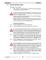
See Graphic: wc_gr000060
When adjusting the ramming stroke, observe the following precautions
to avoid injury to yourself and others.
Adjust stroke with machine standing upright and resting on a firm, level
surface. Do not adjust stroke if the machine is in an unstable position
where it can easily tip or slide.
Always stop engine before adjusting stroke. The clutch could engage,
causing rammer to jump unexpectedly.
Adjustment should be performed by one person and with no one else
near the machine. The tool used to make the adjustment could slip out
of your hands and hit someone standing nearby.
To adjust ramming stroke:
4.9.1
Remove adjusting tool from cover. Open cover.
4.9.2
Check that arrow (a) on center of locking lever is pointing up.
If arrow is pointing down, the spring system is not balanced and could
cause the top half of the rammer to drop unexpectedly while making
the stroke adjustment. To balance spring system, stand behind the
rammer and use guide handle to rock machine back and forth until you
feel the spring system relax. The arrow should now be facing up.
4.9.3
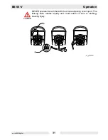
Insert adjusting tool (b) into bore on locking lever. Make sure it is fully
seated so it will not slip out. Steady the rammer by holding guide
handle and use adjusting tool to push locking lever straight down until
it is completely disengaged (refer to Operation 1 in illustration above).
4.9.4
Using the adjusting tool, move locking lever until center arrow is
pointing at the desired stroke setting (Operation 2).
During this adjustment, tension is applied to the spring system. This
tension will release as the locking lever is returned back to its locked
position. When this happens, the rammer will settle, causing the
handle and crankcase to drop down. The movement is slight but
happens quickly. Be aware of this when moving locking lever.
4.9.5
Push or pull the adjusting tool to move the locking lever back to its
locked position (Operation 3). When the locking lever is halfway
between the locked and unlocked position the spring system will settle
and move as described in warning above.
4.9.6
Remove adjusting tool. Close cover and lock it in place with tool.
WARNING
WARNING
WARNING
Содержание BS 65-V
Страница 1: ...Rammer BS 65 V OPERATOR S MANUAL 0176651en 001 0808 0 1 7 6 6 5 1 E N...
Страница 2: ......
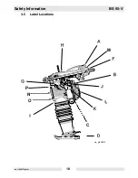
Страница 18: ...Safety Information BS 65 V wc_si000275gb fm 18 3 5 Label Locations wc_gr005418 C P N O M...
Страница 29: ...BS 65 V Operation wc_tx000918gb fm 29 Notes...
Страница 35: ...BS 65 V Maintenance wc_tx000923gb fm 35 wc_gr005326...


