background image

LEYLAND / DAF - Edition 12/2000

WABCO Mannheim

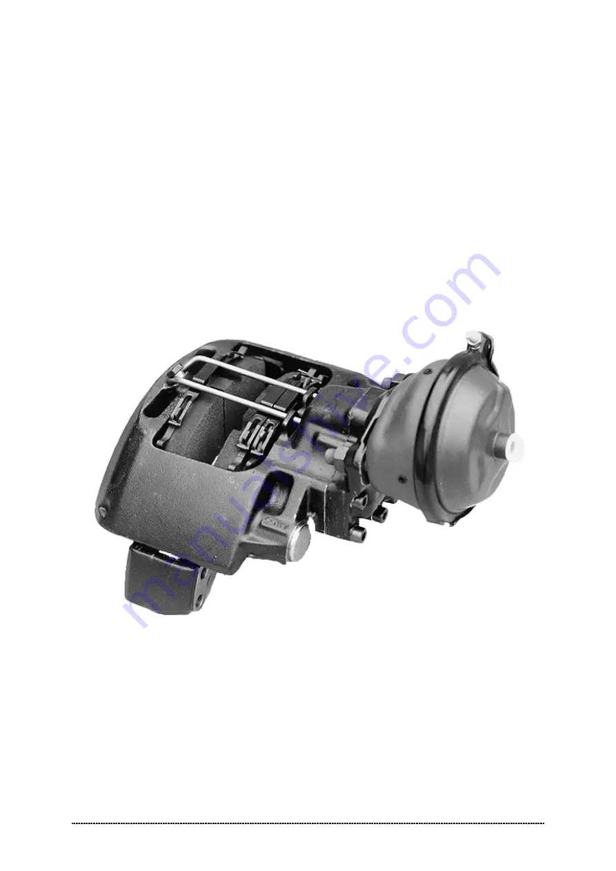
Mechanical Sliding Caliper Disc Brake

Type PAN 17

Assembly and Maintenance Instructions

W ABCO Radbremsen GmbH

  Postfach 71 02 63 – D-68222 Mannheim

Bärlochweg 25 – D-68229 Mannheim

 +49 (0)6 21/48 31-0       

FAX

 +49 (0)6 21/48 31-300

Содержание PAN 17

Страница 1: ...BCO Mannheim Mechanical Sliding Caliper Disc Brake Type PAN 17 Assembly and Maintenance Instructions WABCO Radbremsen GmbH Postfach 71 02 63 D 68222 Mannheim B rlochweg 25 D 68229 Mannheim 49 0 6 21 4...

Страница 2: ...king Adjuster Function 4 2 3 Checking Brake Pads 6 2 4 Checking Brake Discs 6 3 Renewing Brake Pads 8 4 Renewing Brake 14 5 Renewing Gaiters 15 5 1 Renewing Guide Pin Gaiters and Bushes 16 5 2 Renewin...

Страница 3: ...e axially moveable brake pads 35 36 are held in the brake carrier by a hold down hoop 38 and hold down springs 37 Thereby the brake force is then transmitted to the abutment faces in the brake carrier...

Страница 4: ...Disc Brake PAN 17 LEYLAND DAF Edition 12 2000 2 Fig 2 Plan View and Section Fig 3 Side View and Section 39 38 35 36 37 19 21 12 1 2 9 8 7 6 21 19 22 4 5 10...

Страница 5: ...he brake with pressurised air or other high pressure cleaning apparatus Danger of Bodily Injury Keep hands and fingers out of the inside of the caliper to avoid injury A second technician should assis...

Страница 6: ...ide Notice Brake Pads and Thrust Plate stay in place Push the brake caliper towards the wheel and check gap with feeler gauge 0 5 mm Air gap 1 2 mm Notice Always insert feeler gauge between brake cali...

Страница 7: ...ately 1 bar When the adjuster functions properly the closed end wrench will retract in steps in an anticlockwise direction Notice The rotation angle of the closed end wrench will decrease with increas...

Страница 8: ...C Total normal pad thickness new 26 mm After checking the brake pads reposition the cable guide 40 insert the hold down springs 37 and secure the hold down strap 38 with hex head bolt 39 to the brake...

Страница 9: ...error function is indicated Clean a contaminated sensor ring with e g a wire brush A damaged or strong corroded sensor ring is a risk for a good ABS function Therefore in case of damaged or strong cor...

Страница 10: ...es Figures Separate the electrical connector arrow and remove plug Remove hexagon bolt 39 from pad hold down hoop 38 with spanner Table 1 Position II Withdraw pad hold down hoop 38 from caliper 1 Remo...

Страница 11: ...spreader plate 19 arrow by hand at the same time to ensure the pin in the adjuster screw remains engaged in the slot in the spreader plate otherwise there is a danger that the adjuster screw will tur...

Страница 12: ...all defect gaiters according to Section 5 1 and 5 2 Caution In case of a damaged gaiter 10 must be checked if dirt or water has already entered and damaged the inner parts of the brake or the gaiter...

Страница 13: ...en the actuation side and the disc to insert the brake pad Insert spreader plate 19 in the brake carrier and engage with the adjuster screw 21 Caution The spreader plate must sit within the brake carr...

Страница 14: ...irection to close up the pads is anti clockwise Do not fit pad hold down hoop before setting clearance Install new pre assembled wear indicator and cable guide 40 and insert sensor contacts see arrows...

Страница 15: ...the brake caliper and tighten to specified torque Table 1 Position II Remove transport protection cap arrow if present from the plug of wear indicator Install new spring clip 41 in brake caliper and...

Страница 16: ...left Illustration A and right Illustration B brake configurations Do not interchange On the front axle the long guide pin 8 is always located in the back On the rear axle the long guide pin 8 is alwa...

Страница 17: ...er flange on the brake caliper Refit brake pads and spreader plate according to Section 3 Refit the brake cylinder on the caliper and tighten nuts with spanner Table 1 Position V Caution With the brak...

Страница 18: ...ake carrier 2 by removing caps 11 from the guide pins 8 9 in the caliper housing with a suitable tool e g a chisel Caution Take care not to damage cover bores in caliper housing Press the tool against...

Страница 19: ...quences Figures Press in two new bushes 4 for the longer guide pin 8 Firstly A fit the inner bush with the special fitting tool L1 42 0 2 mm and secondly B the outer bush with the special fitting tool...

Страница 20: ...e shorter guide pin 9 is a clearance fit an is located at the brake disc trailing side Remove all excess grease The brake carrier end of the guide pins and the mating surfaces of the carrier must be f...

Страница 21: ...sure differential Mount brake over the brake disc on the axle Tighten hexagon bolts with spanner Table 1 Position III Caution Note the correct fixing order of the hexagon bolts Table 1 Position III In...

Страница 22: ...ake pad so that the adjuster screw cannot be screwed completely out of the adjuster After the thread check remove the brake pad Secure adjuster screw 21 against turning arrow and screw out the adjuste...

Страница 23: ...10 and press the gaiter into the seat in the caliper Shown in Figure without adjuster screw Visually inspect for proper seating Lubricate gaiter 10 lip to ease fitment and fit gaiter 10 into its seat...

Страница 24: ...m brake disc degrease Inspect installed brake disc for run out as described in Section 2 4 Adjust ABS sensor according to vehicle manufacturer s instructions Install brake as described in Section 4 In...

Страница 25: ...n of the brake only the lowest drainage opening on the brake cylinder can be open Before mounting the brake cylinder clean the sealing surface of the brake caliper and lubricate the spherical indentat...

Страница 26: ...isconnect Caution Do not remove brake cylinder with air lines connected Air hoses could be damaged Loosen hex head bolts and remove brake cylinder from brake caliper Fig 65 Fig 66 Installing the Sprin...

Страница 27: ...and tighten Important Observe that the brake lines are connected properly Port 11 Service Foot Brake Port 12 Parking Hand Brake Release hand brake Screw in mechanical release Note The brake lines must...

Страница 28: ...anti clockwise left maximum 3 air gap decrease De adjust clockwise right maximum 12 air gap increase Do not use a power driven socket II 17 X 20 2 III 18 X 205 20 IV 14 X 340 20 Tightening order for g...

Страница 29: ...ear Sensor Wheel Side 5 Guide Pin Gaiters 36 Brake Pad with Wear Sensor Actuation Side 6 Internal Hexagon Bolt long 37 Hold Down Springs 7 Internal Hexagon Bolt short 38 Pad Hold Down Hoop 8 Guide Pin...

Отзывы:

Похожие инструкции для PAN 17