Vulcan-Hart Snorkel SG-1010 Скачать руководство пользователя страница 1


INSTALLATION, SERVICE 

& PARTS MANUAL FOR 

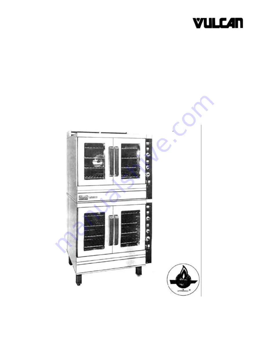
SNORKEL GAS CONVECTION OVEN MODELS: 

SG-22, SG-2SM, SG-1010, SG-10SM 

ELECTRONIC IGNITION MODELS: 

SG-22E, SG-2SME, SG-1010E, & SG-10SME 


VULCAN-HART CORPORATION, 3600 NORTH POINT BOULEVARD, BALTIMORE, MARYLAND 21222 

Содержание Snorkel SG-1010

Страница 1: ...E PARTS MANUAL FOR SNORKEL GAS CONVECTION OVEN MODELS SG 22 SG 2SM SG 1010 SG 10SM ELECTRONIC IGNITION MODELS SG 22E SG 2SME SG 1010E SG 10SME VULCAN HART CORPORATION 3600 NORTH POINT BOULEVARD BALTIM...

Страница 2: ...such work be familiar with all precautions required and have complied with all requirements of state or local authorities having jurisdiction Reference in the United States of America National Fuel Ga...

Страница 3: ...he outside of the building through a ventilation system installed by qualified personnel 6 For an appliance equipped with casters 1 the installation shall be made with a connector that complies with t...

Страница 4: ...WITCH TO THE OFF POSITION OPENING OVEN DOORS WILL AUTOMATICALLY CUT OFF THE FAN AND THE HEATING ELEMENTS BUT IF THE FAN SWITCH IS NOT PUSHED TO THE OFF POSITION HOT AIR GATHERED WITHIN THE OVEN CAVITY...

Страница 5: ...TIONS Continued 114594 12 thru 14 FLUE CONNECTIONS 114594 15 TROUBLE SHOOTING SERVICE 114594 15 16 PARTS DESCRIPTION REPLACEMENT 114594 17 thru 19 POWER PANEL PARTS REPLACEMENT 114594 20 PRESSURE REG...

Страница 6: ...actuated The solenoid is controlled by the thermostat and the Load Control The thermostat must be On and the thermostat and the load control set to an operating position for the solenoid to come On an...

Страница 7: ...solution before operating the unit 6 Mount the upper section on top of the lower sec tion from the front of units Allow the upper section to overhang the lower unit at the front by approx imately 8 i...

Страница 8: ...ly tighten the three screws on the right hand side of the flue extension Loosen the two 5 16 screws located on the lower right hand back of the unit See Detail D 5 Locate the back right hand side exte...

Страница 9: ...oven See Detail G 8 While still facing the front of unit remove six 5 16 screws from the back right hand body side cover See Detail H 9 Return to the back of the unit and face it Loosen four 5 16 left...

Страница 10: ...of the unit disassemble three 5 16 hex head screws from the front right hand body side cover Remove body side cover by placing hands at the top and bottom of cover while lifting upward and then pull a...

Страница 11: ...semble second half of manifold assembly e to SMB section as shown in Detail N 7 Place new full width flue deflector on rear top of stacked units as shown in Detail N 6 Remove the SMT unit from the sta...

Страница 12: ...MB unit See Detail N Reinstall the bottom side manifold cover using fourteen 5 16 hex head bolts See Detail Q and reassemble stacking straps to the SMB and SMT sections 11 Reinstall the SMT manifold c...

Страница 13: ...first two digits of this number indicates the year the second two numbers indicates the month i e YEAR 83 MONTH 10 SERIAL NUMBER 8310 If your unit was built prior to October 1983 proceed to Step b b...

Страница 14: ...ection in line with lower section Install flue closure assembly connecting upper and lower sections with sheet metal screws provided Detail C CA 9 Install connection pipe with unions per Detail D 10 C...

Страница 15: ...to the electric supply 120 volt ovens single phase units are equipped with a 7 ft 3 in wire including ground supply cord 120 volt appliances are equipped with a three prong grounding plug for your pr...

Страница 16: ...bulb located directly below each pilot burner If pilot does not light turn the gas off wait 5 minutes and repeat steps 1 through 5 of 17 It is not necessary to repeat pilot lighting everyday For units...

Страница 17: ...of trouble shooting and repair malfunctions not mentioned in the following paragraphs The instruments necessary for trouble shooting would be A A C Voltmeter to measure line voltages up to 480 volts B...

Страница 18: ...going to the solenoids Problem 3 The oven heats up properly when empty but as soon as the food is put in it the temperature drops and the oven never recovers Procedure Meals containing excessive mois...

Страница 19: ...e front of the switch panel Replace the component in the original position by pushing through the front face of the switch panel until the spring clips lock into place Reconnect wires to proper termin...

Страница 20: ...ng the timer motor when the knob is set to the desired posi tion Once the timer completes its set interval at the zero mark the common terminal disconnects from timer motor shuts the motor off and con...

Страница 21: ...g power to the heat and motor controls When the door opens the normally open contact is de energized and the solenoid and the blower are turned off To adjust or replace the door switch refer to Detail...

Страница 22: ...ol circuits and the lights The circuit breakers are constructed with internal time delay They detect short circuit or overload conditions in the equipment and trip to OFF position E TRANSFORMER The co...

Страница 23: ...See Detail A for location of the pilot Both pilot valves are located in the front center of the burner compartment AIR ADJUSTMENT Although the burner air supply is adjusted before shipment it should...

Страница 24: ...TEMPERATURE TIME IN MINUTES NO of RACKS LOAD CONTROL SETTING Cakes Sheet Cakes 18 x 26 x 1 Pan 5 Med to Med Scaled 4 1 2 to 6 Ibs Per Pan 325 to 360 F 20 to 23 4 Med to Med Scaled 6 to 7 1 2 Ibs Per...

Страница 25: ...nch Fries 400 to 450 F 6 to 8 4 Hi to Med 2 to 3 Med to Med Frozen Lunches TV Dinners 350 to 400 F 10 to 12 4 to 5 Hi to Med 2 to 3 Med to Med Frozen Entrees 3 4 to 1 Thick 300 to 350 F 10 to 20 2 to...

Страница 26: ...NENTS WITH REBUILT CONTROLS ANY UNAUTHORIZED SUBSTITUTION OF CONTROLS AS STATED ABOVE MAY BE A SAFETY HAZARD AND WILL AUTOMATICALLY VOID THE WARRANTY AND THE CERTIFICATION ASSOCIATED WITH THIS EQUIPME...

Страница 27: ...ASSY 111457 G1 1 102 FLUE CLOSURE ASSY 111457 G1 1 111456 2 1 103 FLUE STACK ITEM NO DESCRIPTION PART NO SG 2SMT E UNITS QTY SG 2 SMT E UNITS PART NO SG 2SMB E UNITS QTY SG 2 SMB E UNITS PART NO SG 2...

Страница 28: ...NITS QUANTITY SG 10SM SG 1010 E UNITS 10 RELAY 111497 A2 3 111497 A2 3 11 BUZZER 111499 1 1 111499 1 1 14 PORCELAIN BLOCK 114881 1 1 114881 1 1 16 TRANSFORMER 111500 6 1 111500 6 1 17 TERMINAL BLOCK 3...

Страница 29: ...1 111497 A2 3 11 BUZZER NS 111499 1 1 111499 1 1 14 PORCELAIN BLOCK 114881 1 1 114881 1 1 16 TRANSFORMER 111500 6 1 111500 6 1 17 TERMIMAL BLOCK 3 POLE 110472 8 1 110472 8 1 67 GROND LUG 3 1500 06089...

Страница 30: ...111497 A1 1 111497 A1 1 11 BUZZER 111499 2 1 111499 2 1 14 PORCELAIN BLOCK 114881 1 2 114881 1 2 16 TRANSFORMER 111500 7 1 111500 7 1 17 TERMINAL BLOCK 110472 8 1 110472 8 1 18 FUSE HOLDER NS 113053 1...

Страница 31: ...SG2SMT E UNITS QUANTITY SG2SMT E UNITS PART NO SG 10SMT E UNITS QUANTITY SG 10SMT E UNITS 10 RELAY 111497 A1 3 111497 A1 3 11 BUZZER 111499 2 1 111499 2 1 67 GROUND LUG 3 1500 1 3 1500 1 14 PORCELAIN...

Страница 32: ...SG 22 E UNITS QUANTITY SG2SM SG 22 E UNITS PART NO SG 10SM SG 1010 E UNITS QUANTITY SG 10SM SG 1010 E UNITS 10 RELAY 111497 A1 1 111497 A1 1 11 BUZZER 111499 2 1 111499 2 1 14 PORCELAIN BLOCK 114881 1...

Страница 33: ...2 111496 E4 2 3 THERMOSTAT 111506 3 1 111506 3 1 4 CONTROL KNOB 111242 1 3 111242 1 3 5 INFINITE SWITCH 111503 1 1 111503 1 1 6 TIMER 60 MIN 120V 111690 1 1 111690 1 1 TIMER 60 MIN 240V 111690 2 1 111...

Страница 34: ...GNAL LIGHT 111496 E4 2 111496 E4 2 3 THERMOSTAT 111506 3 1 111506 3 1 4 CONTROL KNOB 111242 1 4 111242 1 4 5 INFINITE SWITCH NS 111503 1 1 111503 1 1 6 TIMER 60 MINUTE 120V 111690 1 1 111690 1 1 6A TI...

Страница 35: ...114678 2 1 71 SOLENOID HOUSING ASSEMBLY 114653 G1 1 114653 G1 1 72 INLET PIPE ASSEMBLY 112380 G1 1 112380 G1 1 74 90 ELBOW FITTING 3 8NPT TO 7 16 CC ST 114800 4 1 114800 4 1 75 FITTING 90 ELBOW 1 4 CC...

Страница 36: ...Y SG 22E SG 1010E 100 SM 2 SPARK MODULE 114806 1 2 4 101 LT HD 58 WIRE WITH ELECTRODE 114805 1 1 2 102 RT HD 30 WIRE WITH ELECTRODE 114805 2 1 2 103 43 U4 PILOT 114658 1 2 4 104 BRACKET 114671 2 1 2 1...

Страница 37: ...36 LAMP SOCKET 21201 20 2 21201 20 2 37 LIGHT BULB 155V 50W FROSTED 107793 2 2 107793 2 2 38 LAMP BOX HOUSING ASSEM 111395 G1 2 111395 G1 2 39 LAMP BOX GASKET NS 111206 1 2 111206 1 2 40 LAMP BOX ASSE...

Страница 38: ...1 1 59 LEFT RIGHT NOZZLE TUBE 114619 1 2 114619 1 1 60 BURNER SPUD NAT NS 10901 36 2 10901 33 2 60A BURNER SPUD PROPANE NS 10901 52 2 10901 53 2 61 BURNER ASSEMBLY 112709 G1 2 112709 G2 2 80 MAIN GAS...

Страница 39: ...T 112629 1 1 112629 1 1 63 MOUNTING BOLT 102085 20 4 102085 20 4 64 MOTOR SPACER 112630 1 4 112630 1 4 65 LOCK NUT 104084 9 4 104084 9 4 66 MOTOR 120V OR 208 240 1 PH 111205 5 1 111205 5 1 Motor 480V...

Страница 40: ...49 SHUT OFF VALVE NS 111420 1 1 111420 1 1 50 REGULATOR 6 RV43A NAT GAS NS 108279 9 1 108279 1 1 50A REGULATOR 10RV 43 PROPANE GAS NS 108279 3 1 108279 3 1 52 TEE FITTING NS 114614 1 1 114614 1 1 53 C...

Страница 41: ...TS QUANTITY SG 10SM SG 1010 E UN ITS 100 OVEN PILOT PROTECTION 114644 1 2 114644 1 2 101 LEFT RIGHT SUPPLY TUBING 114635 1 2 114635 1 2 55 MAIN GAS SUPPLY TUBING 114620 1 1 114620 1 1 52 TEE 7 16 CC 1...

Страница 42: ...NITS PART NO SG 10SM SG 1010 E UNITS QUANTITY SG 10SM SG 1010 E UNITS 102 BURNER 114646 1 2 114646 2 2 103 OVEN PILOT 114645 1 2 114645 1 2 104 LEFT HAND PILOT TUBE 114658 1 1 114658 1 1 105 RIGHT HAN...

Страница 43: ...ART NO SG 2SM SG 22 E UNITS QUANTITY SG 2SM SG 22 E UNITS PART NO SG 10SM SG 1010 E UNITS QUANTITY SG 10SM SG 1010 E UNITS 102 BURNER 114646 1 2 114646 2 2 103 OVEN PILOT 114645 1 2 114645 1 2 NOTE FO...

Страница 44: ...6 F1 1 111496 F1 1 85 MICRO SWITCH SUPPORT 110619 1 1 110619 1 1 86 MICRO SWITCH INSULATION 3 LONG NS 111365 1 2 111365 1 2 87 DOOR ADJ BRACKET 111139 1 4 111939 1 4 88 HINGE PIN BEARING 104629 2 4 10...

Страница 45: ...12845 1 2 112845 2 2 26 DRIP TRAY NS 111429 1 1 111429 3 1 26A DRIP TRAY SS NS 111429 2 1 111429 4 1 27 RIGHT HAND SIDE LINING 112697 1 1 112697 5 1 28 LEFT HAND SIDE LINING 112697 2 1 112697 6 1 29 R...

Страница 46: ...97 CONTROL COVER 114630 1 1 114630 1 1 98 CONTROL COVER 114642 1 1 114642 1 1 99 PANEL UPPER EXT ASSEMBLY SMT UNITS 114629 G1 1 114629 G1 1 99A PANEL UPPER EXT ASSEMBLY T UNITS 114629 G3 1 114629 G3 1...

Страница 47: ...ASSEMBLY 114594 G1 I S P MANUAL FOR SG 22 22E 2SM 2SME SG 1010 1010E 10SM 10SME CONVECTION OVEN SIGN MANUAL 114594 G1 SUB NO SHEET PART NUMBER AFFECTED DATE DML 5 114594 1 thru 114594 46 12 27 84 114...

Отзывы: