15
Fault code
Alarm overview
Alarm
priority
E01
Alarm from rotor guard
”C”
E02
Excessive supply voltage
”C”
E03
Insufficient supply voltage
”C”
E04
Power to the motor increased at a critical level, e.g. short- circuiting
cable, connector or motor
”C”
E05
Excessive temperature inside OJ-DRHX (>95°C)
”NC”
E06
Blocked motor
”C”
E07
No valid Modbus communication >10 sec.
”C”
E08
Phase fault on stepper motor power supply (U, V, W)
”C”
E09
Internal hardware error
”C”
Table 10 Fault codes
3.4 Modbus and 0-10V control
Rotary Wheel driver can be controlled via Modbus RTU, according to the Modbus protocol or via analogue 0-10 V input
signal. The device is factory-set for 0-10 V control – after detection of a start signal or speed setpoint via Modbus, it
will automatically shift temporarily to control via Modbus RTU (the ”0-10 V” signal is then ignored). The function is
automatically reset when the device is restarted.
3.4.1 Modbus control
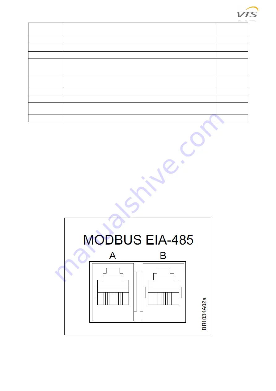
Modbus can be connected to the controller via the two RJ12 connectors (connectors "A" and "B" are internally parallel
connected and it is therefore optional which connector is used) or via spring terminals in the terminal strip. For RJ12
connectors, we recommend the use of telecom cable, 6-wire, unshielded, 30 AWG/0.066mm² (flat/telecom cable) and
round communications cable (like twisted pair cables) for the spring terminal connectors.
Figure 20 RJ12 Modbus connectors


