14
3.3.4 Display
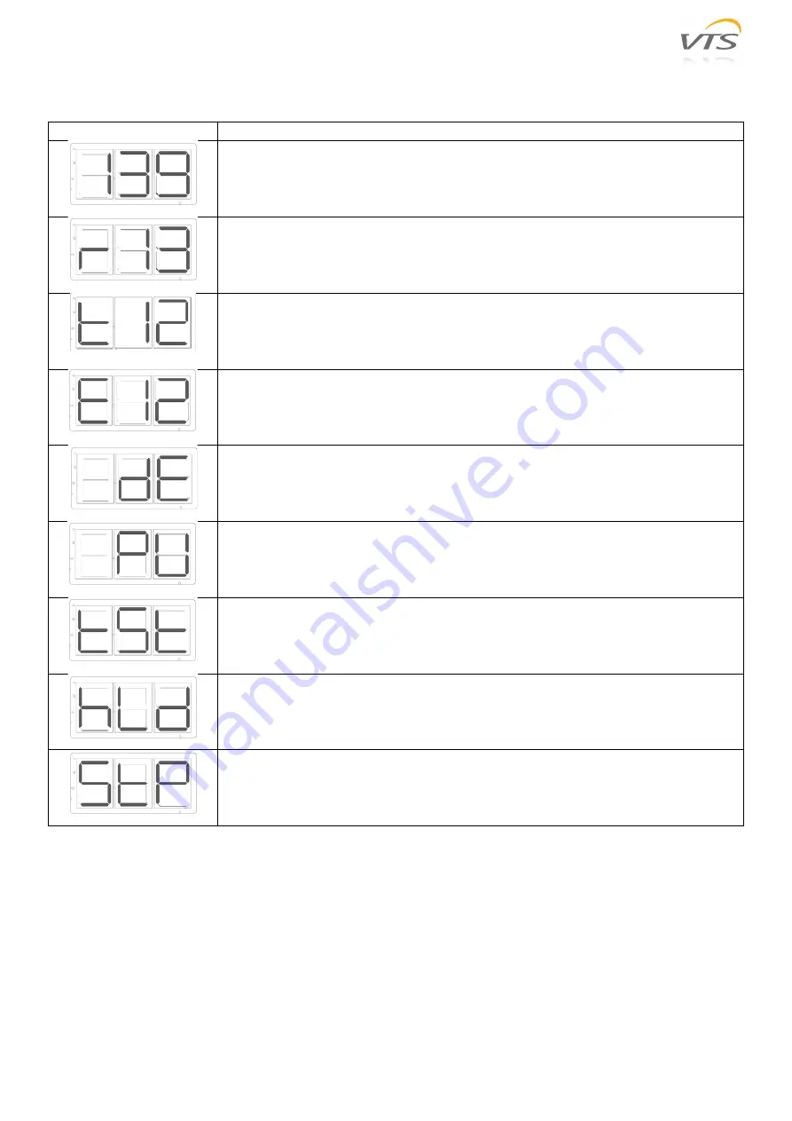
Display is visible with open and closed cover. The display shows current status for drive, stepper motor and rotor.
Code
Description
Current stepper motor speed is displayed when the stepper motor is running and no
rotor or pulley diameter has been entered via respective corresponding Modbus
registers.
Current rotor speed is displayed when the stepper motor is running and rotor and
pulley diameter have been entered via respective corresponding Modbus registers.
Display toggles between torque and speed with 2 sec toggle intervals.
Current torque (Nm) Display toggles between torque and speed with 2 sec toggle
intervals.
Fault codes - see the importance of the individual fault codes in the Table 10.
Reduced performance operation due to current overload, overheating or other failure
or overload. Read out the current fault/alarm via Modbus – Table 13.
Purging function activated.
Test function is activated and stepper motor is receiving control signal for max. RPM
rotations.
Hold function is activated (Holding).
Stepper motor is in “STOP” mode.
Table 9 Display statuses
The driver has a built-in alarm monitor, which monitors optimal fault-free operation and triggers an alarm
if operating or performance problems are observed. Alarms are either ”Critical” or ”Non-critical”. ”Critical” alarms stop
the stepper motor. ”Non-critical” alarms reduce stepper motor performance. The built-in alarm monitor stops the
device. If the alarm situation passes, the alarm is automatically reset and the driver is restarted.
If the maximum number of restarts (5 times/60 min) is exceeded, the alarm must be reset. The alarm can be reset
by means of a Modbus command. The alarm is automatically reset if the power is disconnected for longer than 60
seconds. Alarm/fault code is shown on the display. Alarms can also be read via Modbus – see Table 13.


