voidacoustics.com
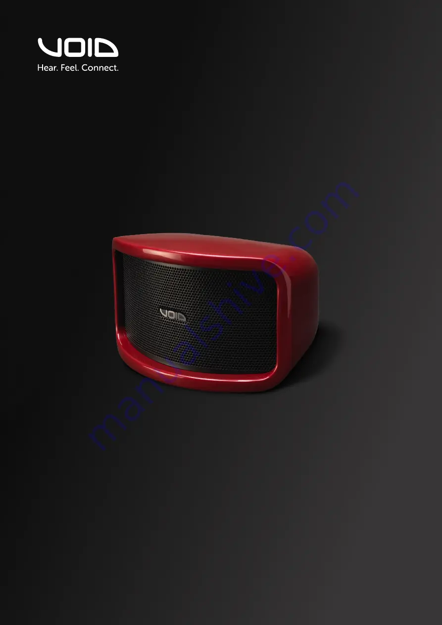
Cyclone 55
Compact styling, impressive sound
U S E R G U I D E V 2 . 0
Страница 1: ...voidacoustics com Cyclone 55 Compact styling impressive sound USER GUIDE V2 0...
Страница 2: ...t notice For the latest online version visit www voidacoustics com Void Acoustics and the Void logo are registered trademarks of Void Acoustics Research Ltd in the United Kingdom USA and other countri...
Страница 3: ...Cyclone 55 Specifications 7 3 5 Cyclone 55 Dimensions 8 4 Cable and Wiring 9 4 1 Electrical Safety 9 4 2 Cable Considerations for Fixed Installations 9 4 3 Phoenix Connector 9 4 4 Cyclone Glanded Con...
Страница 4: ...e of causing permanent hearing damage from prolonged exposure The higher the sound level the less exposure needed to cause such damage Avoid prolonged exposure to the high sound levels from the loudsp...
Страница 5: ...mplete or any of its contents are found to be damaged inform the shipping company and inform your dealer When you are removing your Cyclone Series loudspeaker from its original packaging Cyclone Serie...
Страница 6: ...safely and ensure it performs to its full capability 3 2 Cyclone 55 overview The Cyclone 55 offers high levels of fidelity and definition from an ultra compact and visually appealing format in a weath...
Страница 7: ...2 x 5 LF 2 x 1 soft dome HF tweeters Dispersion 110 H x 70 V Connectors Phoenix connectors with link out Height 192 mm 7 6 Width 309 mm 12 2 Depth 207 mm 8 1 Weight 3 2 kg 7 1 lbs Enclosure Fibreglas...
Страница 8: ...Page 8 UG10583 2 0 Cyclone 55 User Guide V2 0 3 About 3 5 Cyclone 55 dimensions Figure 3 3 Dimensions...
Страница 9: ...owing standards IEC 60332 1 Fire retardancy of a single cable IEC 60332 3C Fire retardancy of bunched cables IEC 60754 1 Amount of Halogen Gas Emissions IEC 60754 2 Degree of acidity of released gases...
Страница 10: ...bolts from the rear of the connector plate Undo the glanded connectors from the rear of the connector plate and remove the rubber plugs from the connectors Insert the cable through the glanded connec...
Страница 11: ...ge 11 UG10583 2 0 Cyclone 55 User Guide V2 0 Attach the cable to the phoenix connector then position the connector plate and attach it using the M6 bolts Figure 4 5 Phoenix attachment 4 Cable and Wiri...
Страница 12: ...lone 55 User Guide V2 0 1 HF 5 LF Passive Crossover 1 HF 5 LF Passive Crossover 4 5 Cyclone 55 wiring diagram Phoenix pins 1 1 Phoenix pins 2 2 In HF 2 x 1 and LF 2 x 5 Link out Figure 4 7 Wiring diag...
Страница 13: ...igure 4 9 Bias Q1 Q2 output connection Bias D1 Q1 Q2 Out 1 Output LF 2 x 5 and HF 2 x 1 Max parallel units 4 2 load to amplifier 1 1 Figure 4 11 Bias Q5 Bias Q3 Q5 Out 1 Output LF 2 x 5 and HF 2 x 1 M...
Страница 14: ...to their assistants to the venue staff and to the public Before lifting any part of the system above head height check the whole rig for loose tools or other items that may fall and cause injury Do n...
Страница 15: ...required 4 mm Allen key T51 Wall Bracket White IT2992 supplied Black IT3031 supplied Figure 5 2 Bolt removal Step 1 Remove all four M6 bolts from the rear of the loudspeaker Step 2 Remove the mounting...
Страница 16: ...e it is secure lift the loudspeaker with the mounting plate fixed to it into position and fix it to the bracket using the M6 countersink bolt that was removed in step 2 Step 5a When adjusting the loud...
Страница 17: ...g the loudspeaker into position if the intention is to have maximum horizontal rotation then use adjust the bracket to the configuration shown in figure 5 6b Max horizontal rotation 54 Max vertical ro...
Страница 18: ...cket White IT3802 Black IT3354 4 mm Allen key 19 mm spanner Figure 5 7 T51 ceiling bracket Step 1 Remove the mounting plate from the bracket by removing the M12 bolt as shown Figure 5 8 Mounting plate...
Страница 19: ...ure 5 10 Mounting plate Step 4 Fix the bracket to the ceiling using all eight bolts Once it is secure lift the Air 8 with the mounting plate fixed to it into position and fix it to the bracket using t...
Страница 20: ...T3438 White IT3439 Figure 5 12 T51 stud bracket Step 1 Remove all four M6 bolts from the rear of the loudspeaker Figure 5 13 Bolt removal Step 2 Attach the stud bracket using all four M6 bolts The pro...
Страница 21: ...cket Black IT3727 White IT3728 Figure 5 15 T51 pole bracket kit Step 1 Remove all four M6 bolts from the rear of the loudspeaker Figure 5 16 Bolt removal Step 2 Attach the pole bracket kit using all f...
Страница 22: ...oduct Note that your dealer will need to see a copy of your sales receipt as proof of purchase so please have this to hand when applying for return authorisation 6 2 Shipping and packing consideration...
Страница 23: ...a typical production unit shall be as follows the usable on axis bandwidth shall be 70 Hz to 23 kHz 3 dB and shall average 110 directivity pattern in the horizontal axis and 70 in the vertical one 6 d...
Страница 24: ...usa voidacoustics com HEAD OFFICE Void Acoustics Research Ltd Unit 15 Dawkins Road Industrial Estate Poole Dorset BH15 4JY United Kingdom Call 44 0 1202 666006 Email info voidacoustics com Void Acoust...