


5 Application Examples
5.1 Motor Overload Protection
The thermal model used for motor overload in the MCD
500 has two components:
•
Motor windings: These have a low thermal
capacity and affects the short term thermal
behaviour of the motor. This is where the heat is
generated by the current.
•
Motor Body: This has a large thermal capacity and
affects the long term behaviour of the motor. The
thermal model includes considerations for the
following:
•
Motor current, iron losses, winding
resistance losses, motor body and
winding thermal capacities, cooling
during run and cooling at standstill.
•
The percentage of the rated capacity of
the motor. This sets the displayed value
for the winding model and is affected
by the motor FLC setting amongst
others.
NOTE
1-1 Motor FLC
should be set to the motor's rated FLC. Do
not add the overload rating as this is computed by the
MCD500.
The thermal overload protection used in MCD500 has a
number of advantages over the thermal relays.
•
The effect of fan cooling is accounted for when
the motor is running
•
The actual full load current and locked rotor time
can be used to more accurately tune the model.
The thermal characteristics of the windings are
treated separately from the rest of the motor (ie.
the model recognises that the windings have low
thermal mass and high thermal resistance).
•
The winding portion of the thermal model
responds very rapidly compared with the body
portion, meaning the motor can be run closer to
its safe maximum operating temperature while
still being protected from thermal damage.
•
The percentage of motor thermal capacity used
during each start is stored in memory. The starter
can be configured to automatically determine
whether or not the motor has sufficient thermal
capacity remaining to successfully complete
another start.
•
The memory function of the model means that
the motor is fully protected in “warm start”
situations. The model uses data from the real
time clock to account for elapsed cooling time,
even if control power has been removed.
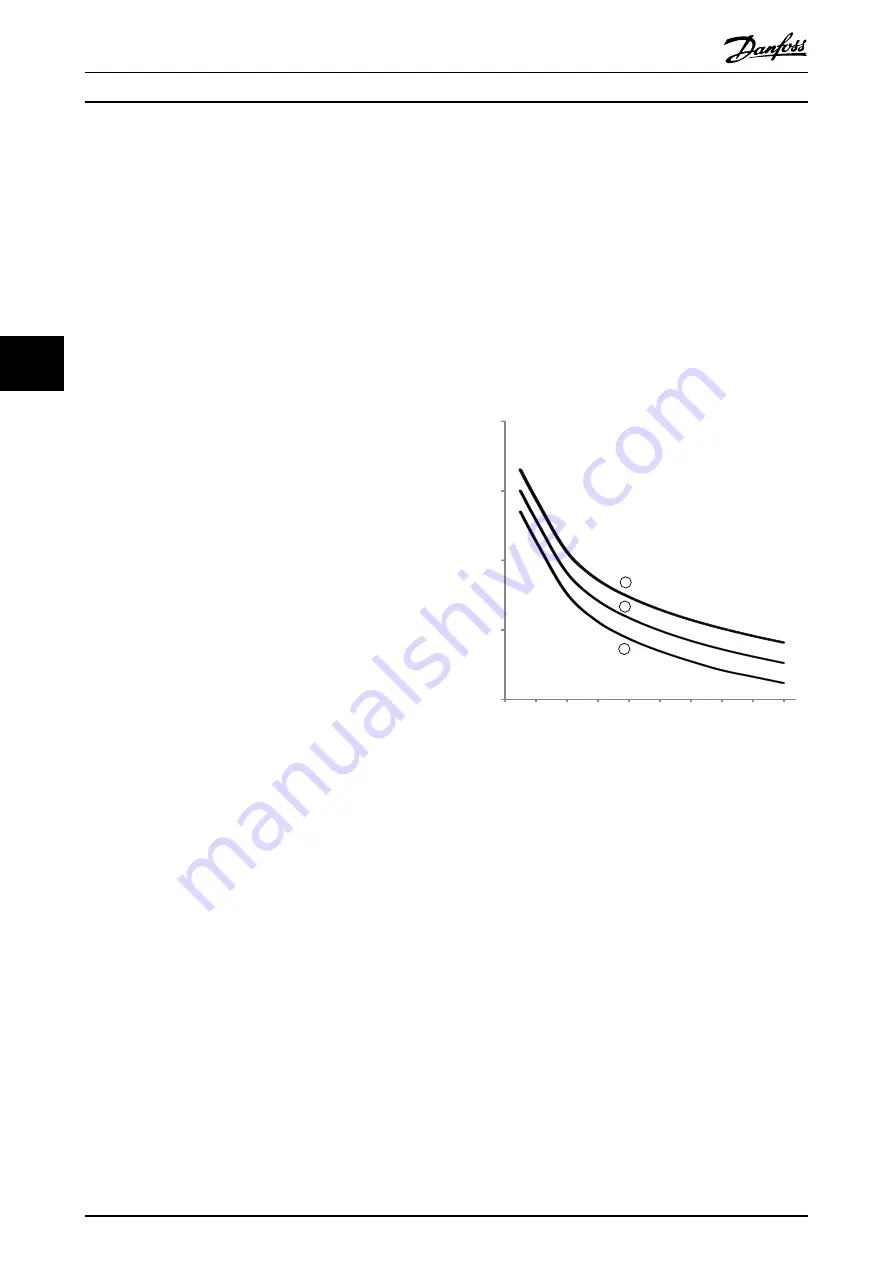
The overload protection function provided by this model is
compliant with a NEMA 10 curve, but will provide superior
protection at low levels of overload due to the separation
of the winding thermal model.
100
200
300
1
10
100
1000
10000
177HA596.10
Time in seconds to reach 100% of thermal model
Current (%motor full load current)
3
1
2
400
500
600
700
800
900 1000
Illustration 5.1
1.
MSTC
1
= 5
2.
MSTC
1
= 10
3.
MSTC
1
= 20
1
MSTC is the Motor Start Time Constant and is defined as
the Locked Rotor Time (in
1-2 Locked Rotor Time
) when the
Locked Rotor Current is 600% of FLC.
5.2 AAC Adaptive Acceleration Control
AAC Adaptive Acceleration Control is a new form of motor
control based on the motor's own performance character-
istics. With AAC, the user selects the starting or stopping
profile that best matches the load type and the starter
automatically controls the motor to match the profile. The
MCD 500 offers three profiles - early, constant and late
acceleration and deceleration.
Application Examples
MCD 500 Operating Instruction
30
MG17K402 - VLT
®
is a registered Danfoss trademark
5
5