CONFIDENTIAL – DO NOT COPY
Page 9-4
File No. SG-0243
Yes
N0
N0
Yes
N0
N0
N0
N0
N0
Yes
Yes
Yes
Yes
Yes
N0
Yes
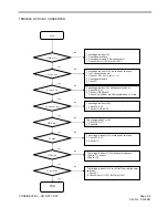
TROUBLE
OF
DC-DC
CONVERTER
Start
J1 PIN 9 10,11,
J1 PIN 2,3,4,5
The voltage is about + 12V while power switch on
1. Is J1 connection good
2. Check J1
Pin1 is up to about 3.3V?
3. Check power board
4. Check F1
The voltage is about + 5V
1. Check power board
2. Check power cable, F2 & connection J1
3. Check U8 pin1 (+5V) & pin2 (+3.3V)
U1 pin 5 6 7 8
The voltage is about +5V while power switch on
1. Check F2 & U1
2. Check
OPWRSB (R20)
3
. Check U1 pin1&2 or pin 3&4, should have -1V more.
U2, U8 & U33 pin2
The voltage is about +3.3V
1. Check F2 & U1
2. Check U2, U4 & U33
CE15 pin 1
The voltage is about +1.6V
1. Check F2 & U1
2. Check U6
U10 pin2
The voltage is about +2.6V while power switch on
1.Check J1 Connect
2.Check U10
L7 pin2
The voltage is about +1.2V while power switch on
1. Check F2 & U1
2. Check U5
END
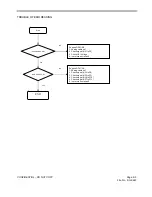
U3 pin1 & pin3
The voltage is about +12V to +5V(for Tuner)while power
switch on
1. Check F1
2. Check U3 pin1 (+12V) & U3 pin3 (+5V)


