MA-BCKS-5.6 Models
MA-BCKS-7.0 Models
Installation & User Manual
Please read this manual thoroughly before operating the device
and keep this document for future reference
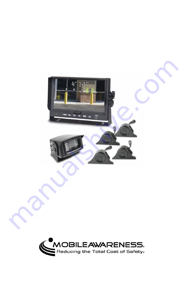
VisionStat Plus
®
Video Monitoring and
Obstacle Detection Sensor Systems
www.mobileawareness.com


