pictor M1817
Commissioning
© Vision & Control GmbH 2014
999.994.528.10-en-1.4
40
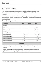
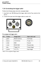
7.3.5 Connecting the trigger cable
Perform the following steps only in de-energiesed state:
1. Insert the 6-pin HIROSE plug of the trigger cable into the Trig. socket on the
device.
2. Connect the open end of the trigger cable to control unit.
Video
LAN
Trig.
I/O
1
2
3
4
5
6
Pin assignment trigger cable
Pin
Colour
Assignment
Open cable end
1
green
RS232 TxD Out
Send data
2
brown
+5 V DC Out
Power +5 V
3
white
GND
Ground
4
violet
RS232 RxD
Receive data
5
grey
Trigger Out
Output trigger
6
yellow
+5 V TTL
Input trigger
Table 14: Pin assignment trigger cable

