


VT DSO-2A20 Manual Rev. 1.1
Virtins Technology
Roll Mode is activated by ticking the above “Roll” button in the Sampling Parameter Toolbar.
Under this mode, the oscilloscope frame is split into many segments with the length of each
segment equal to the Roll Width, which is set via [Setting]>[Display]>“Roll Mode”> “Roll
Width” (in points). The data displayed in the oscilloscope window will shift left by a step of
one Roll Width each time when a new segment of data arrives. The newly arrived data will
be shown in the right most portion of the graph. You can consider using Roll Mode if the
sweep time is too long (e.g. greater than 1 s) to avoid long time waiting for screen update.
The Roll Mode button is enabled when the Record Length per sweep is four times or more of
the Roll Width. Under the Roll Mode, whether the acquired data are continuous (i.e. the
adjacent segments of data are connected smoothly without missing any data in between) or
not depends on the system throughput, sampling frequency, bit resolution, number of
sampling channels, etc.
1.8.3 Oscilloscope Digital Trigger and Trigger Frequency Rejection
The second-generation VT DSOs use hardware based DSP algorithm for triggering and
trigger frequency rejection. This greatly improves the trigger stability and accuracy, even
with noisy signals.
1.8.3.1 Digital Triggering
The second-generation VT DSOs use a digital trigger instead of the conventional analog
trigger. The digital trigger is implemented through hardware. It is able to search for the
trigger event in the digitized samples in real time. Trigger jitter is a significant problem in
conventional analog trigger. It is caused by the disparity between the acquisition and trigger
circuits. Trigger jitter causes the waveform displayed on the screen to shift left and right as
the display is updated. A digital trigger, on the other hand, does not have this kind of jitter as
it shares the same physical path with the acquisition.
The Multi-Instrument software also features a specially designed algorithm which effectively
eliminates the lateral shaking of waveform display due to limited sampling rate compared
with the signal frequency (i.e. very few samples acquired per signal cycle).
1.8.3.2 Trigger Noise Rejection
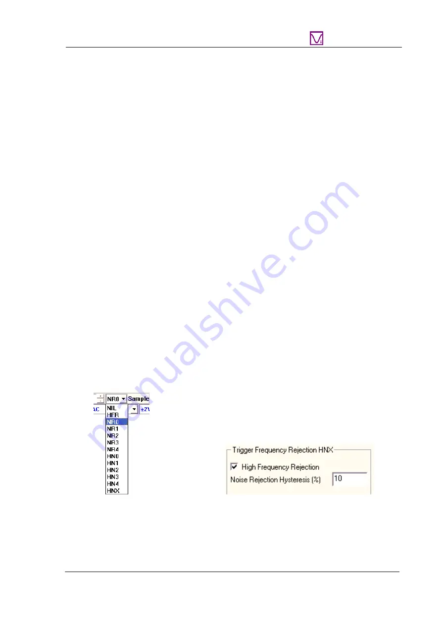
Trigger Frequency Rejection can be used to filter out noises from the trigger signal to prevent
false triggering. The available options are: NIL (All-Pass), HFR (High Frequency Rejection),
NR0~NR4 (Noise Rejection), HN0~HNX (High Frequency Rej Noise Rejection).
There are different levels of noise rejection. For Levels 0~4, the hysteresis values are fixed
while for Level X, it is user-configurable via [Setting]>[ADC Device]> “Trigger Frequency
Rejection HNX”. You can configure whether to include high frequency rejection and specify
www.virtins.com 19 Copyright © 2017 Virtins Technology


