background image

AM PLL High Power Medium-Wave Transmitter 


A High-Power version of AM Transmitter, operating between 620KHz and 1024KHz in the 

Medium Waveband (AM Band) and are designed to be reliable and stable units.  

They can deliver up to 20 watts of RMS power into a short length aerial. This equates to 80 

watts peak power cleanly driven up to 100% modulation. 

This transmitter has been designed to operate into a fairly short ‘long-wire’ aerial, minimum 

length approximately 12 metres and up to 25 metres. Anything shorter than this is very 

inefficient and may make critical components overheat. Obviously the longer the better. 

Each Transmitter circuit design employs a Colpitts FET oscillator in a Phase-locked loop 

circuit for accuracy and ease of frequency selection.  It is also very stable and therefore does 

not drift off frequency. The Phase Lock circuit provides selection in 1KHz steps, so that the 

unit can be used in either Europe, which has 9KHz spacing between channels, or in the USA 

and other parts of the World where 10kHz is used between channels. A rugged Power 

MOSFET is also used on the RF output stage, which drives the output toroid and variable 

tuning capacitor. High voltage rated components are used in the output section. 

Audio modulation is series-derived using Power Transistors. It is driven by an audio level 

control chip which allows the transmitter to always achieve maximum modulation, 

whatever the audio source and nominal level is, within reason. (CD player, mixer, PC etc) 

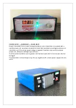
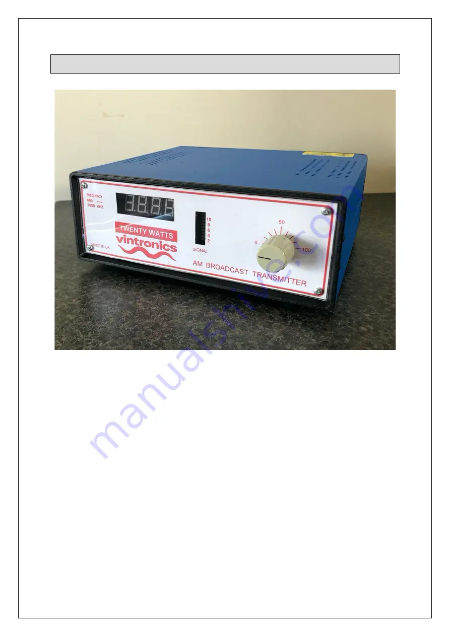
Housed in a Steel box with ABS front and rear panels. Ventilation holes to improve air flow 

for component cooling. A fan is used on higher output models where necessary.   

Содержание AM PLL

Страница 1: ...nd ease of frequency selection It is also very stable and therefore does not drift off frequency The Phase Lock circuit provides selection in 1KHz steps so that the unit can be used in either Europe which has 9KHz spacing between channels or in the USA and other parts of the World where 10kHz is used between channels A rugged Power MOSFET is also used on the RF output stage which drives the output...

Страница 2: ...nside the transmitter are voltage sensitive and could burn out if the wrong power voltage is applied Therefore only use the supplied power unit otherwise damage may well occur It will be evident whether a wrong power unit has been used which in turn causes internal damage The transmitter comes already set up for use together with a mains power supply and wire aerial ...

Страница 3: ...roid which is used for better aerial matching At higher frequencies in particular if the tuning capacitor is at one end use the link to select a lower inductance for improved matching Much better matching can be achieved by moving the link Remove top cover to gain access A longer aerial wire can be used with the transmitter and will give a better range Excellent results have been obtained using a ...

Страница 4: ...with signal efficiency and distance A copper stake in the ground is a good start Search the Internet for further advice Maximise the signal level with the tuning control whilst observing the signal level LED display Or even better is the use of a Field Strength Meter which are readily available on eBay It is possible to fine tune the operating frequency by adjusting VC1 on the main circuit board s...

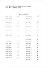
Страница 5: ...ng dip switches On the rear of the transmitter there are a set of dip switched numbered 1 to 10 Using the frequency table set the switches to the desired frequency On the High Power unit for example if your desired frequency is 1017Khz look it up in the table and you will see its binary setting to the left As we can see the binary position for 1017 is 110100000 The switch positions are up for 1 an...

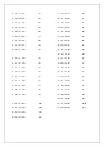
Страница 6: ... 0 0 1 0 1 690 1 0 1 0 1 0 0 1 0 1 693 1 1 1 0 0 0 0 1 0 1 700 1 1 0 0 0 0 0 1 0 1 702 1 1 0 0 1 1 1 0 0 1 710 1 0 0 0 1 1 1 0 0 1 711 1 1 1 1 1 0 1 0 0 1 720 1 1 1 1 1 0 1 0 0 1 720 1 0 1 1 0 0 1 0 0 1 729 1 1 0 1 0 0 1 0 0 1 730 1 1 0 1 1 1 0 0 0 1 738 1 1 1 0 1 1 0 0 0 1 740 1 0 0 1 0 1 0 0 0 1 747 1 1 0 0 0 1 0 0 0 1 750 1 1 1 0 1 0 0 0 0 1 756 1 1 1 1 0 0 0 0 0 1 760 1 0 1 0 0 0 0 0 0 1 765 1...

Страница 7: ...0 1 0 1 0 0 1 1 1 0 0 909 1 1 0 0 0 1 1 1 0 0 910 1 1 0 0 1 0 1 1 0 0 918 1 1 1 1 0 0 1 1 0 0 920 1 0 0 0 0 0 1 1 0 0 927 1 1 0 1 1 1 0 1 0 0 930 1 1 1 1 0 1 0 1 0 0 936 1 1 1 0 0 1 0 1 0 0 940 1 0 1 1 1 0 0 1 0 0 945 1 1 0 0 1 0 0 1 0 0 950 1 1 0 1 0 0 0 1 0 0 954 1 1 1 1 1 1 1 0 0 0 960 1 0 0 1 1 1 1 0 0 0 963 1 1 0 1 0 1 1 0 0 0 970 1 1 1 0 0 1 1 0 0 0 972 1 1 1 0 1 0 1 0 0 0 980 1 0 1 0 1 0 1 ...

Страница 8: ...ing an oscilloscope for maximum but not over modulation depth Without breaking carrier solid line at 0 Hum cancel This is accomplished by adjustment of VR1 This is best done whilst operational It introduces a low level 30 60 Hz signal into the drive RF level monitor The Bargraph is a visual representation of carrier level and Modulation The signal is detected by the mini RF sniffer aerial inside a...

Страница 9: ...hold until it flashes to set this and press to hold for exit to save setup Technical Specifications 20 Watt Unit Size 220mm wide 240mm depth 90mm high Weight 1 45Kg Power requirement DC 24 28 V 2 5A max Audio input RCA Phono sockets left and right audio between 75mV and 775mV RMS Audio Bandwidth 3dB 80Hz to 6KHz Modulation level up to 100 RF Output level Average 20 Watts dependant on Frequency and...

Отзывы: