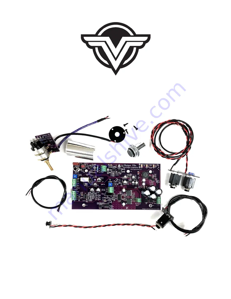
VINTAGE VIBE WURLY AMP KIT
INSTALLATION / INSTRUCTION MANUAL
Страница 1: ...VINTAGE VIBE WURLY AMP KIT INSTALLATION INSTRUCTION MANUAL...
Страница 2: ...what is involved and perhaps offer some tips ideas that you may find helpful If after reviewing the material you are not confident in your ability to successfully perform the installation we recommen...
Страница 3: ...one Speaker Out Installation Instructions Final Steps Set Up Page 22 RCA Cable Replacement Page 23 FX Loop Installation Page 25 Additional Notes Page 30 Instructions and wiring kit apply to console mo...
Страница 4: ...adphone Output and Aux Output 2 Outer Tremolo Knob Controls the depth of the tremolo When set fully counter clockwise the effect is bypassed The effect becomes deeper as the knob is turned clockwise 3...
Страница 5: ...ffectively mute the Speaker Headphone output signal This can be useful during some recording and live performance situations If no connection between speakers or a headphone jack are made to the ampli...
Страница 6: ...nsertion of effects into the signal path within the amplifier circuitry The result is that the signals at the Aux Output and Speaker Headphone Output will both be affected accordingly The FX Loop jack...
Страница 7: ...that secured the AC inlet earth ground wire to the rail as you will need to re install this at the end of the installation 2 Detach power transformer secondary wires blue red red red yellow from stoc...
Страница 8: ...to Potentiometer 200 200A or Rotary Switch Chopped Console from the control bracket 5 Desolder or clip the Orange wire at the Headphone Jack Desolder or clip the Black wire at the Headphone Jack termi...
Страница 9: ...del Only There will be two black wires soldered to one of the terminals on the Right Speaker Determine which wire s other end terminates at the stock amplifier PCB and desolder or clip it from the spe...
Страница 10: ...racket Re secure jack bracket and Speaker Molex Connector for 200A models using existing screw and nut 8 200A Model Only Remove Aux Output Trimpot from piano base 9 Temporarily remove cable clamps fro...
Страница 11: ...Manual MAY 2020 200A Amplifier 11 Dress power transformer primary wires Desolder primary wires from AC terminal strip 200A Model Only Remove wires from tube Unscrew metal bracket and remove tube the t...
Страница 12: ...ist primary wires and run them to the AC terminal strip along the back edge of the rail Secure the wires to the rail with the included foil shielding tape Trim excess tape as necessary Resolder primar...
Страница 13: ...l Remove any remaining glue Drill out the revealed hole with a 1 4 bit and remove any burrs Install LED Bezel through the front of the control bracket 13 Install new Vintage Vibe Wurly Amp PCB on rail...
Страница 14: ...to the Volume Potentiometer Connect the other end of the cable to PCB connector J4 PCB J4 Cable V 3 Black Wire Wpr Red Wire Gnd Heatshrinked Shield 16 Install Tremolo Potentiometer PCB and Cabling In...
Страница 15: ...e black Connect the wires to PCB connector J3 PCB J3 Purple Cable Gnd Heatshrinked Shield D 1 Black Wire D 3 Red Wire PCB J3 Black Cable F 1 Black Wire F 3 Red Wire 17 If installing LED indicator Inst...
Страница 16: ...itch on the amplifier PCB S1 or insert a TS or TRS plug into the Headphone Jack Do not utilize a cable for this task Minimum Speaker Load is 4 1 Install new Aux Output Headphone Jack PCB Assembly Sold...
Страница 17: ...Clear Wire Gnd Heatshrinked Shield Connect Red and Black wires from Aux Output Headphone Jack Assembly PCB to Amplifier PCB connector J5 PCB J5 Wires from Jack PCB Speaker Out Red Wire Speaker Out Bla...
Страница 18: ...rom the AC inlet through the two cable clamps behind the PCB and reinstall it at the threaded hole near the power transformer using the original hardware 5 200A Model Only Connect speaker wiring Molex...
Страница 19: ...ece of equipment DI etc To shut off the speakers either engage the Speaker Cut switch on the amplifier PCB S1 or insert a TS or TRS plug into the Headphone Jack Do not utilize a cable for this task Mi...
Страница 20: ...assembly into the plate at front left cheek block of the piano using provided lock washer finish washer and nut Do NOT over torque Use provided 1 8 cable clamp to hold wire in place with front left r...
Страница 21: ...When drilling your hole make sure you ve provided adequate space for not only the jack plate but also the Headphone Jack PCB to be installed as shown above AND that your hole does not infringe on the...
Страница 22: ...peakers headphone output are to be utilized set speaker cut switch to ON 5 Plug unit in at wall outlet and power on 6 Level Adjust VR3 and Aux Output VR4 trim pots are shipped set at 50 level First se...
Страница 23: ...rlitzer was originally outfitted with a 200 or 200A amplifier unit 200A 1 Install the new cable to the mounting bracket using the screws you removed when uninstalling the preamplifier PCB 200 1 Remove...
Страница 24: ...Amp Manual MAY 2020 3 Add the new cable s conductor terminal lug to the harp at the same location as the existing jumper wire lug 4 Screw down the new cable s shield terminal lug along with the groun...
Страница 25: ...the rail and connect the cable to PCB connector J7 as shown below 200 additional drilling required Install at 200A Aux Output Trim pot location as shown above 200 200A additional drilling required In...
Страница 26: ...nstallation and 6 1 4 from the rear edge of the piano Mark this position for drilling 3 Drilling Use a 3 4 paddle or forstner bit Cheek block location Drill from the top down until the center tip of t...
Страница 27: ...all the three mounting screws provided Aux Output Trim or Mirrored Location Hold Jack PCB and Plate assembly in location so that the jack is centered over the hole in the piano base Mark your hole loc...
Страница 28: ...emove it from the PCB If desoldering be careful not to damage the PCB as this would void any warranty Connect cable to PCB connector J7 9 If you wish to remove the FX loop at any time simply install a...
Страница 29: ...29 Vintage Vibe Rev 1 0 Wurly Amp Manual MAY 2020...
Страница 30: ...sure the correct polarity between the speakers and the PCB connector It is recommended to use a minimum of 20AWG cable For 200 200A models simply break off the Headphone Jack portion of the Jack PCB 3...