Viale Vicenza, 14
36063 Marostica VI - Italy
www.vimar.com
49400575B0 04 2002
Eikon TACTIL
21122
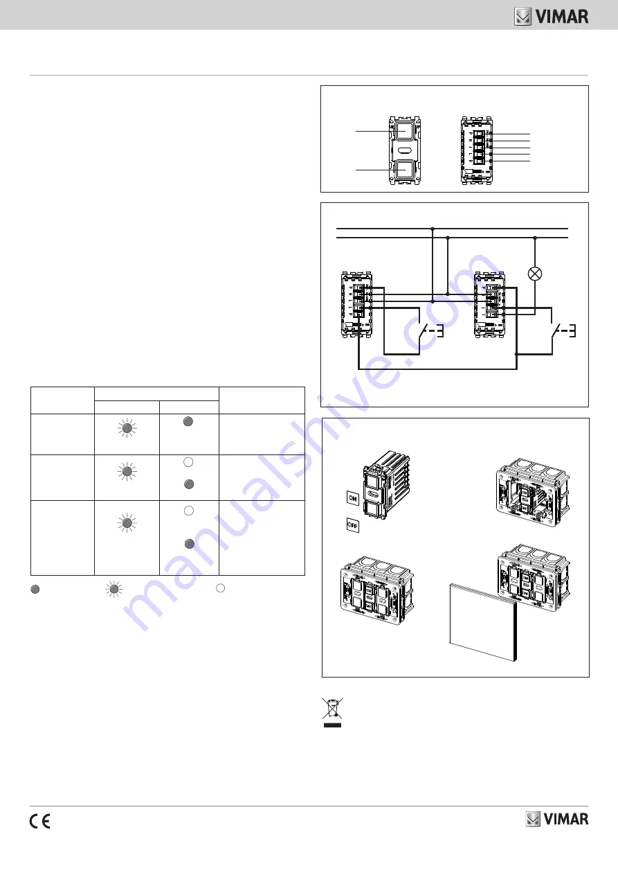
FRONT AND REAR VIEW
LED
top
button
LED
bottom
button
P
N
L
L
N
CONNECTIONS
21122
21119
L
R
N/O push-
button
N/O push-
button
INSTALLATION
1.
2.
3.
4.
Electronic remote control, 2 buttons for remote management of a single elec-
tronic control or for central control of multiple commands, to be completed with
Eikon Tactil cover plate and label.
FEATURES.
• Rated supply voltage: 230 V~, 50/60 Hz
• Indicator lights with interchangeable symbols for identification in the dark.
• Touch button recalibration: 1 minute
• Operating temperature: -5 °C - +35 °C.
CONTROLLABLE LOADS.
• Coded output (terminal R): 230 V~, 50 mA max
• When connected to devices 21119, 21134 and 21174 the appliance provides remote control
over their loads (maximum distance 100 m)
OPERATION.
• Front indicator lights always on
• Controls: double touch button on the front; controls are made by lightly placing a finger on the
front of the device over the illuminated indicator light
•
The buzzer is always enabled when configuring
CAUTION: The circuit load should be considered always powered.
N.B: Each time the cover plate is installed, wait at least 1 min. for it to be recalibrated.
CONFIGURATION.
With the load/lamp switched off, press both buttons under the cover plate simultaneously. The top
button will start blinking and enter configuration phase 1:
- tap on the
bottom
button
to change the settings of the selected configuration
- tap on the
blinking top button
to save the selected phase and move on to the next phase of
configuration.
If no operations are performed within 15 s, the device will exit the configuration without saving
the last phase.
CONFIGURATION
SETTING
PROCEDURE
Top button LED
Bottom button LED
PHASE 1
Change brightness
1 repeated blink
Always on
at the set bright-
ness
Press the bottom button to
change the brightness cycli-
cally (low, medium, high)
PHASE 2
Enable buzzer
2 repeated blinks
Buzzer off
Buzzer on
Press the bottom button to
switch the buzzer on/off
PHASE 3
Enable
scenario
(to be used when
you need to control
different devices
simultaneously)
3 repeated blinks
Scenario
disabled (default)
Scenario only OFF
enabled
Press the bottom button
to enable or disable the
scenario behaviour
LED on
LED blinking
LED off (default)
INSTRUCTIONS.
Connect the appliance as indicated in the "CONNECTIONS" illustration. The power circuits (L-N)
should be protected against overloading by installing a device, fuse or circuit breaker, with rated
current not exceeding 10 A.
INSTALLATION RULES.
• Installation should be carried out by qualified staff in compliance with the current regulations
regarding the installation of electrical equipment in the country where the products are installed.
• The device can be installed on Eikon Tactil cover plates with 2, 3 and 4 modules; use the dedicated
blank module art. 21041 to close the unused modules.
• When installing with a BS 5M cover plate (2+blank+2), thus on the mounting frame art. 20609,
the device cannot be installed in the central module of the mounting frame; this module should
be closed by using the blank module art. 21041 (for details, see
SC-Card on www.vimar.com ->
Products -> Product Catalogue
at the article code).
• On the same cover plate used for art. 21122 it is not possible to install SELV Tactil devices (art.
21520, 21540, 21840, 21860).
REGULATORY COMPLIANCE.
LV directive. EMC directive. Standard EN 60669-2-1.
REACH (EU) Regulation no. 1907/2006 – Art.33. The product may contain traces of lead.
For all details on possible installation architectures, please refer to SI-Installation Diagrams for the
relevant item code at www.vimar.com -> Products -> Product catalogue.
WEEE - Information for users
If the crossed-out bin symbol appears on the equipment or packaging, this means the product must
not be included with other general waste at the end of its working life. The user must take the worn
product to a sorted waste center, or return it to the retailer when purchasing a new one. Products
for disposal can be consigned free of charge (without any new purchase obligation) to retailers with
a sales area of at least 400 m
2
, if they measure less than 25 cm. An efficient sorted waste collection
for the environmentally friendly disposal of the used device, or its subsequent recycling, helps avoid
the potential negative effects on the environment and people’s health, and encourages the re-use
and/or recycling of the construction materials.


