17
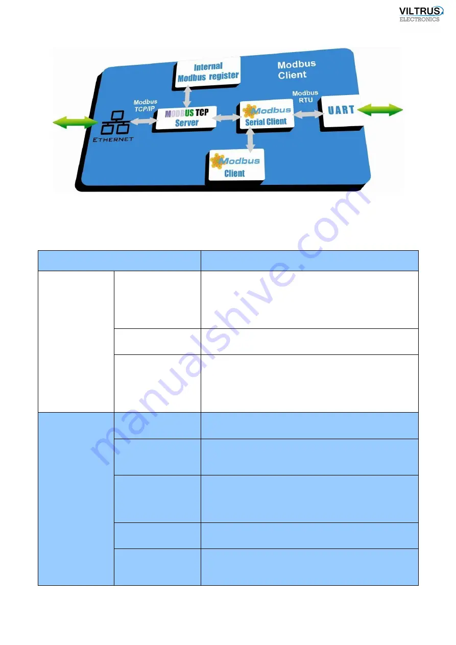
Pic 3
Scheme of data logger in Modbus Client mode
4.2
Measuring functions
FUNCTION
DESCRIPTION
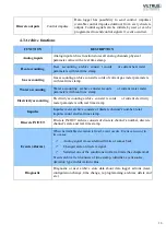
Analog inputs
Measurement
Data logger periodically 0.1 second intervals measures
analog signal in default measurement scale of electrical
signals (Voltage, current, resistance). To eliminate
fluctuations in measured signal data logger uses time and
amplitude filters.
Conversion
Measured analog signal is converted into physical
parameter value.
Min/Max alarm limit
Accepted values data logger compares with user-defined
min/max alarm limit. If parameter value goes out of range
or comes back (min/max alarm limit) deviation (event)
fixed. For more information about events and alarms see
chapter
4.4.
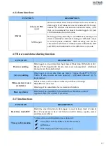
Discrete inputs
Discrete IN purpose
Can be used for discrete IN state follow either as
impulse meter or alarm signal.
Current state
Data logger periodically tracks all discrete inputs‘ status
and during change on each channel it stores current state
change with real time value.
Impulse meter
Each discrete channel can be used as impulse counter. All
summed impulses are stored in data logger’s memory.
Physical value is converted from impulse quantity
number multiplied by multiplier.
Alarm state
By discrete channel‘s state (Open, Close, Both cases)
function initiates alarm.
Archive state
By discrete channel‘s state (Open, Close, Both cases)
input can be written to archive. For more information
about archive see chapter
4.3.
Содержание MX-7
Страница 1: ...2 ...
Страница 4: ...5 9 6 USB cable 85 9 7 Installing VILTRUS USB driver 85 9 8 TCP IP settings 87 ...
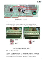
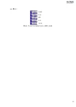
Страница 22: ...23 see Pic 6 3 6 V 5 V 6V 8 V 10 V Pic 6 Power for external device DIP switch ...
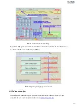
Страница 53: ...54 Pic 48 Routing configuration example ...
Страница 54: ...55 Pic 49 Routing screenshots ...
Страница 59: ...60 2 Set COM port number UART port must be configured and assigned to COM client on ...
Страница 66: ...67 Pic 61 Setting up RAY 1 as External module by example ...
Страница 75: ...76 Pic 71 Records in archives section Archives Configutation ...


