Viglen Limited
Quick Start Guide
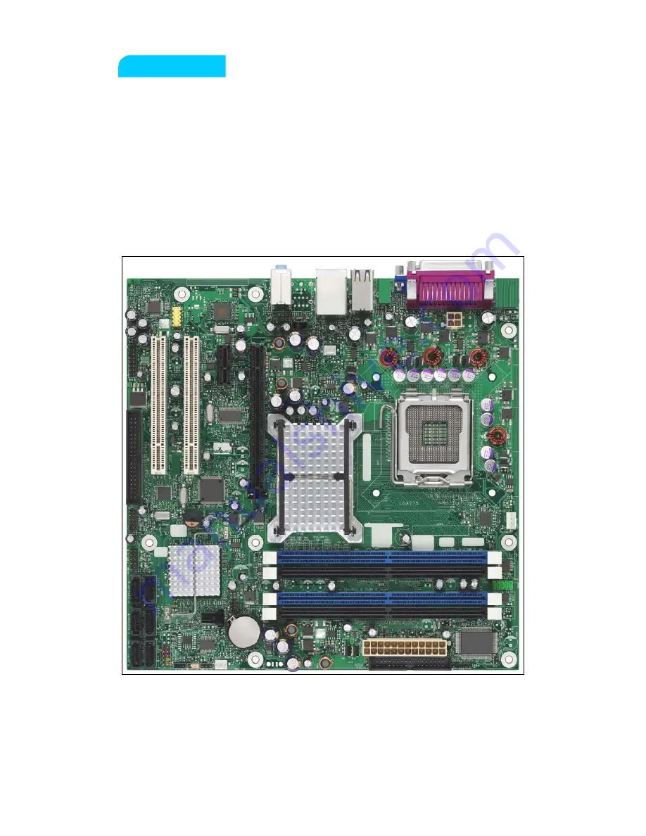
Viglen Product Description:
Intel D965GF Motherboard
Viglen order Code:
PMPGF001
Viglen System:
Genie (S775)
Product Photograph:
Page - 1 - of 21
Страница 1: ...Viglen Limited Quick Start Guide Viglen Product Description Intel D965GF Motherboard Viglen order Code PMPGF001 Viglen System Genie S775 Product Photograph Page 1 of 21 ...
Страница 2: ... No CPU speed FSB L2 cache E6300 E6400 E6600 E6700 1 86 2 13GHz 2 40 2 66GHz 1066MHz 1066Mhz 2MB 4MB 805 820 840 915 960 2 66GhZ 2 80Ghz 3 40GHz 2 80GHz 3 60GHz 533MHz 800MHz 800MHz 2MB 2MB 4MB 505 506 520 571 630 672 2 66GHz 2 66GHz 2 80GH 3 80Ghz 3 00GHz 3 80GHz 533MHz 800MHz 800MHz 1MB 1MB 2MB 310 355 352 356 2 13 3 33GHz 320GHz 333GHz 533MHz 533MHz 256KB 512KB Front side bus speed 1066MHz 800M...
Страница 3: ...s 1 x Audio Out Rear I O connectors 1 x MIC Memory type DDR2 Supports Unbuffered non registered single or double sided DIMMs Non ECC memory Serial Presence Detect SPD memory only For RIMMs install CRIMM in empty sockets N A Number of memory sockets Four 240 pin DDR2 1 8 V SDRAM Dual Inline memory Module DIMM sockets Maximum memory support Support up to 8GB of system memory using DDR2 667 or DDR2 5...
Страница 4: ...B 925 3 GHz 800 MHz 2x2 MB 920 2 80 GHz 800 MHz 2x2 MB 915 2 80 GHz 800 MHz 2x2 MB 840 3 20 GHz 800 MHz 2x1 MB 830 3 GHz 800 MHz 2x1 MB 820 2 80 GHz 800 MHz 2x1 MB Intel Pentium D 805 2 66 GHz 533 MHz 2x1 MB 670 3 80 GHz 800 MHz 2 MB 661 3 60 GHz 800 MHz 2 MB 660 3 60 GHz 800 MHz 2 MB 651 3 40 GHz 800 MHz 2 MB 650 3 40 GHz 800 MHz 2 MB 641 3 20 GHz 800 MHz 2 MB 640 3 20 GHz 800 MHz 2 MB 631 3 GHz ...
Страница 5: ...346 3 06 GHz 533 MHz 256 KB 345J 3 06 GHz 533 MHz 256 KB 341 2 93 GHz 533 MHz 256 KB 340J 2 93 GHz 533 MHz 256 KB Intel Celeron D 336 2 80 GHz 533 MHz 256 KB Page 5 of 21 ...
Страница 6: ...lug proceed as follows The wire which is coloured green and yellow must be connected to the terminal in the plug which is marked by the letter E or by the safety Earth symbol Ω or coloured green or green and yellow The wire which is coloured blue must be connected to the terminal which is marked with the letter N or coloured black The wire which is coloured brown must be connected to the terminal ...
Страница 7: ...t remove the component from its anti static protective packaging until you are about to install it 3 Hold boards by the edges try not to touch components interface strips etc Note We recommend that you return your computer to the service department for upgrading Any work carried out is fully guaranteed Upgrades should only be carried out by persons who are familiar with handling IC s as incorrect ...
Страница 8: ...nnectors T BIOS Setup configuration jumper block F Processor core power connector U Auxiliary front panel power LED header G Rear chassis fan header V Front panel header H LGA775 processor socket W Serial ATA connectors 6 I Intel 82Q965 GMCH X Front panel USB header J Processor fan header Y Speaker K DIMM Channel A sockets Z Front panel USB header L Serial port header AA Parallel ATE IDE connector...
Страница 9: ...to be easily upgraded in the future without having to resort to buying a whole new case Simply change the I O shield to match the Motherboard The I O shield provides external access to onboard VGA port Parallel Port six USB connectors as well as one LAN Port and audio connectors Figure 2 Back Panel Connectors Table 2 Item Description Item Description A Parallel port Burgundy E Audio line in Retask...
Страница 10: ...1 USB2 HD Audio Link Audio and Serial connector headers The location and or details of these internal headers are shown below Figure 3 Figure 3 Internal Headers Table 3 Item Description A Front Panel connectors B Alternative Front Panel Power LED C USB1 USB2 D Intel HD Audio Link E Audio HD AC 97 F Serial Page 10 of 21 ...
Страница 11: ...or Comments 1 3 HD LED This goes to the Hard Disk L E D on the front panel which lights up when the SATA Hard Disk is in use 2 4 Power LED This attaches to the power L E D on the front panel to display if the computer is active or not 5 7 Reset switch connector When these pins are shorted it will cause the computer to perform a cold reboot 6 8 Power On Off When these pins are shorted it turns the ...
Страница 12: ...etup program The table below shows the jumper settings for the BIOS Setup program modes Table 5 Function Mode Jumper Setting Configuration Normal default 1 2 The BIOS uses current configuration information and passwords for booting Configure 2 3 After the power On Self Test POST runs the BIOS displays the Maintenance menu Use this menu to clear passwords Recovery None The BIOS attempts to recover ...
Страница 13: ... board should be populated with DIMMs that support the Serial Presence Detect SPD data structure This enables the BIOS to read the SPD data and program the chipset to accurately configure memory settings for optimum performance If non SPD memory is installed the BIOS will attempt to correctly configure the memory settings but performance and reliability may be impacted or the DIMMs may not functio...
Страница 14: ...nnels are equal Technology and device width can vary from one channel to the other but the installed memory capacity for each channel must be equal If different speeds DIMMs are used between channels the slowest memory timing will be used Single channel Asymmetric mode This mode is equivalent to single channel bandwidth operation for real world applications This mode is used when only a single DIM...
Страница 15: ...el single channel or flex mode DIMM 0 of Channel A must always be populated This is a requirement of the ICH8 Manageability Engine feature Dual Channel Interleaved Mode Configurations Figure 7 shows a dual channel configuration using two DIMMs In this example the DIMM0 blue sockets of both channels are populated with identical DIMMs Figure 7 Dual Channel Interleaved Mode Configuration with Two DIM...
Страница 16: ...wo DIMMs in Channel A equal the capacity of the single DIMM in the DIMM0 blue socket of Channel B Figure 8 Dual Channel Interleaved Mode Configuration with Three DIMMs Figure 9 shows a dual channel configuration using four DIMMs In this example the combined capacity of the two DIMMs in Channel A equal the combined capacity of the two DIMMs in Channel B Also the DIMMs are matched between DIMM0 and ...
Страница 17: ...e the combined capacity of the two DIMMs in Channel A does not equal the capacity of the single DIMM in the DIMM0 blue socket of Channel B Figure 11 Single Channel Asymmetric Mode Configuration with Three DIMMs Flex Mode Configuration NOTE The use of flex mode requires DIMMs to be installed in both channels Figure 12 shows a flex mode configuration using two DIMMs The operation is as follows The 5...
Страница 18: ...ory and board Before installing or removing memory disconnect the system from AC power and wait for the LED to go off before proceeding The motherboard has two on board power indicators a 5 V standby power indicators green LED and a memory power indicator red LED shown in Figure 15 The 5 V standby power indicator Figure 13 A is lit when there is standby power still present on the board even when t...
Страница 19: ...IMM by the edges remove it from its anti static package 4 Position the DIMM above the socket Align the small notch at the bottom edge of the DIMM with the keys in the socket see inset in Figure 14 B 5 Insert the bottom edge of the DIMM into the socket 6 When the DIMM is inserted push down on the top edge of the DIMM until the retaining clips snap into place Make sure the clips are firmly in place ...
Страница 20: ...puter s cover 4 Gently spread the retaining clips at each end of the DIMM socket The DIMM pops out of the socket 5 Hold the DIMM by the edges lift it away from the socket and store it in anti static package 6 Reinstall and reconnect any parts you removed or disconnected to reach the DIMM sockets 7 Replace the computer cover and reconnect the AC power cord Figure 15 Removing DIMMs Page 20 of 21 ...
Страница 21: ...tel PRO Network Connections 11 1 36 3MB 19 July 2006 Management Engine AFSC 2 0 18 118 2 06 15 August 2006 Graphics Intel Graphics 14 21 1 4642 11 1MB 25 July 2006 Intel R Active Management Technology Serial Over LAN iAMT SOL 5 1 2600 9403 2 0MB 6 June 2006 RAID Intel Storage Program 6 10 1002 16 8MB 30 August 2006 RAID Storage Image F6 driver disk 6 1 0 1002 411KB 30 August 2006 Trusted Platform ...