32
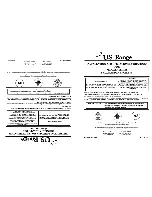
Buffer temperature sensor connection
Plug
)
: Buffer temperature sensors
1
9
2
3
4
5
6
Fig. 25
Connection for 5 buffer temperature sensors
Plug assign-
ment
)
Function with 5 sensors
Additional infor-
mation
Sensor type
1
Buffer temperature sensor 1 (top)
Pt1000
2
Buffer temperature sensor 2
Pt1000
3
Buffer temperature sensor 3
Pt1000
4
Buffer temperature sensor 4
Optional
Pt1000
5
Buffer temperature sensor 5
Optional
Pt1000
6
GND (for all 5 sensors)
—
Connecting heating circuits, solar circuit, DHW, etc.
Various parts of a heating system can be connected to
the boiler control unit. The associated appliances can
be directly connected to the HKK PCB or to extension
kits (via KM-BUS).
!
Please note
Incorrect connections may cause malfunctions.
Observe the instructions provided in this chap-
ter.
Part of heating system
Abbreviation
Max. quantity
Connect
Heating circuit
HC
4
Sensor, pump, mixer motor
Solar circuit
SOL
1
Sensors, pump, mixer motor
DHW heater
TWE
1
Sensor, pump
DHW circulation pump
ZP
1
Pump
Circulation pump for transferring
heat from the DHW cylinder.
Additional solar function
UP
1
Pump
Flow limiter
VSB
1
Valve
Power supply for DHW circulation pump
DHW circulation pumps equipped with their own inter-
nal control unit must be connected via their own sepa-
rate mains connection. Mains connection via the Eco-
tronic control unit or Ecotronic accessories is
not
per-
missible.
Note
For a detailed overview of connection options, see
"Connection options at the HKK PCB and extension
kits via KM-BUS"
Installation sequence
Electrical connections
(cont.)
5679249
Installation