21
1
1
1 (HC)
3 (DHW)
-
2
0
1 (HC)
3 (HC)
-
2
1
1 (HC)
3 (HC)
5 (DHW)
3
0
1 (HC)
3 (HC)
5 (HC)
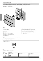
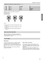
Example for the S1 rotary selector settings of the
extension kits for:
■
2 heating circuits
■
1 DHW heating
2 3 4
5
6
10
9 8 7
2 3 4
5
6
10
9 8 7
2 3 4
5
6
10
9 8 7
A
B
C
Fig. 20
A
Rotary selector, extension kit, heating circuit 1 (set
value: 1)
B
Rotary selector, extension kit, heating circuit 2 (set
value: 3)
C
Rotary selector, extension kit, DHW heating (set
value: 5)
Other electrical connections
Make other electrical connections according to the
"System examples" document and the connection and
wiring diagrams from page 61.
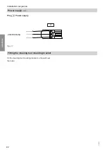
Power supply
Regulations
Connect the power supply and implement all safety
measures (e.g. RCD circuit) in accordance with
IEC 60364-4-41, the connection requirements of your
local power supply utility and VDE or national regula-
tions.
Protect the power cable to the control unit with an
appropriate fuse/MCB.
Mains isolator requirements
For combustion equipment to DIN VDE 0116, the
mains isolator installed on site must comply with the
requirements of DIN VDE 0116 "section 6" [or local
regulations].
Fit the mains isolator outside the installation room.
Ensure that it can isolate
all
non-earthed conductors
simultaneously with at least 3 mm contact separation.
Installation sequence
Electrical connection, extension kit for…
(cont.)
5684984
Installation


