


Installation
24
Assembly instructions
VITOBLOC 200 BM-190/238
5780045
GB
4.8
Exhaust gas connection
4.8.1 General requirements
CAUTION
Observe the maximum permitted back
pressure of 15 mbar when
dimensioning the exhaust gas line and
provide proof of the calculation.
The flow velocity must not exceed
10 m/sec. .
ATTENTION
We urgently recommend providing 2
consecutive exhaust gas sound
absorbers when using the block-type
thermal power station in residential
areas to comply with the demands of
spaces requiring special protection.
4.8.2 Special installation notes
●
Preferably connect the module to the stack by a
separate exhaust line.
●
Make the exhaust gas line acid- and pressure-
proof, preferably with steel 1.4571 (including
insulation) with a wall thickness of at least 1 mm.
●
Install horizontal exhaust pipes with a fall of at least
3 % towards the CHP unit and provide them with
additional condensate drains including siphons.
●
The exhaust gas system has to have qualification
approval with finished systems, be pressure-proof
and
pulsation-resistant to 50 mbar
. Leaks may
not be any more than 0.006 l/m³s (in conformity
with H1) at this test pressure.
NOTE
Special provisions should be observed
if several modules are connected via
manifold.
●
Install the following in the exhaust gas line:
-
Mating flange to the block-type thermal power
plant outlet flange, to correspond to connection
dimensions in chapter 2.
-
Axial expansion joint with stainless steel bellows
for isolation of structure-borne noise and
compensation of heat stress (fit
directly
onto on
the module).
-
Exhaust secondary silencer according to VDI
2058-1, designed for the special requirements of
the ignition frequency noise;
-
Cleaning and water drain sockets as well as
exhaust thermometer and a separate measuring
port;
-
It may be necessary to install an opening in the
outer wall to connect to the stack, with cover
tube and insulation.
●
Insulate the complete exhaust gas system.
(Maximum permitted surface temperature is 50 °C)
●
It may only be started up when a successful
sealing check has been documented or the design
of the pipe system used is approved at registration
(refer to Chapter 5).
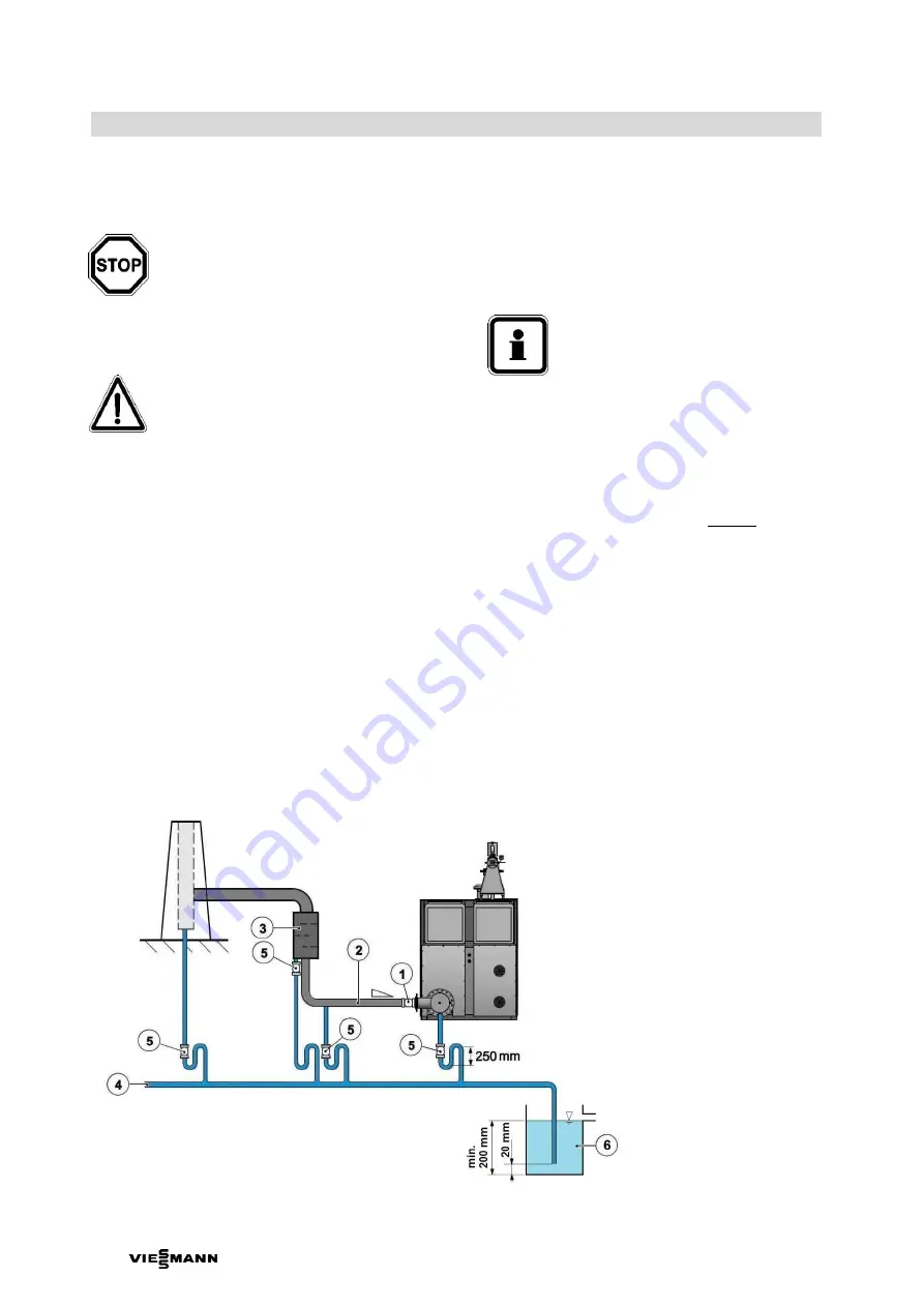
Fig. 12 Scheme showing the peripheral exhaust gas system of two cogeneration modules with condensed water drain pipe and
drainage of safety valves (dimensions in mm)
1
Axial expansion joint
2
Exhaust pipe
3
Secondary exhaust silencer
(option)
4
Condensate drain
5
Flexible connector
(transparent silicone hose
to the fill level control)
6 Gully with water seal


