73
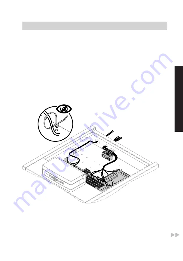
■ Route LV leads < 42 V and
cables > 42 V/230 V~/400 V~
separately.
■ Strip the insulation from the
cables as close to the terminals
as possible, and bundle tightly
to the corresponding terminals.
■ Secure cables with cable ties.
This ensures that, should there
be an error, for example when
detaching a wire, the wires can-
not drift into the adjacent voltage
area.
When routing the on-site power cables,
observe the location of the cable entries
into the appliance through its back panel
(see page 11).
< 42 V
230 V
1.
Route LV leads through the "< 42 V"
aperture to the heat pump control unit
wiring chamber and apply strain relief
using the cable ties provided.
2.
Route 230 V~ cables and power
cables for the compressor through
the "230 V~" aperture to the heat
pump control unit wiring chamber and
apply strain relief using the cable ties
provided.
Installation sequence
Electrical connections
(cont.)
5609 667 GB
Installation
Содержание 7452609
Страница 68: ...68 Removing the top panel 1 Installation sequence Siting the heat pump cont 5609 667 GB...
Страница 125: ...125 Opening the casing door Troubleshooting Maintenance cont 5609 667 GB Service...
Страница 145: ...145 0017 0015 0012 0016 0013 0023 0022 0014 0024 Parts lists Electrical equipment type BWS cont 5609 667 GB Service...
Страница 183: ...183 5609 667 GB...


