background image

4 of 20

Viega Multifunctional Thermostat User Guide

UG-HC 566441 1219 Multifunctional Thermostat (EN)

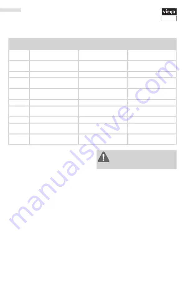
Terminal

2 Heat 2 Cool 

Conventional System

2 Heat 2 Cool 

Heat Pump System

3 Heat 2 Cool 

Heat Pump System

RC

Transformer power

(cooling)

Transformer power 

(cooling)

Transformer power 

(cooling)

RH

Transformer power

(heating)

Transformer power 

(heating)

Transformer power 

(heating)

C

Transformer common

Transformer common

Transformer common

B

Energized in heating

Heat pump changeover 

valve energized in cooling

Heat pump changeover 

valve energized in heating

O

Energized in cooling

Heat pump changeover 

valve energized in cooling

Heat pump changeover 

valve energized in cooling

G

Fan relay

Fan relay

Fan relay

W/E

First stage of heat

First stage of emergency 

heat

First stage of emergency 

heat

Y

First stage of cool

First stage of heat & cool

First stage of heat & cool

Y2

Second stage of cool

Second stage of cool

Second stage of cool & 

second stage of heat

W2

Second stage of heat

Auxiliary heat relay,  

second stage of heat

Auxiliary heat relay,  

third stage of heat

This thermostat is shipped from the factory to operate 

a conventional heating and cooling system. See 

“Programming the Thermostat” on page 10 to 

configure the thermostat for other applications.

WARNING!


All components of the control system 

and the thermostat installation must 

conform to Class II circuits per the NEC Code.

Terminal Designations

Содержание 15118

Страница 1: ...o updates For the most current Viega technical literature please visit www viega us Pick an installation location that is easy for the user to access The temperature of the location should be representative of the building Installation Tips Applications Guide The Multifunctional Heat Cool Thermostat can be use for the following applications Gas or Oil Heat Electric Furnace Heat Pump No Aux or Emer...

Страница 2: ...Subbase Attaching the Thermostat to the Subbase Align the 4 tabs on the subbase with corresponding slots on the back of the thermostat then push gently until the thermostat snaps in place To insure a solid fit between the thermostat and the subbase Mount subbase to a flat wall or electrical box Use screws provided Drywall anchors should be flush with the wall Wires should be pushed into the wall A...

Страница 3: ...n In systems with no emergency heat relay a jumper can be installed between E and W2 to turn thermostat into a single stage control Thermostat Wiring If you are replacing a thermostat make note of the terminal connections on the thermostat that is being replaced In some cases the wiring connections will not be color coded For example the green wire may not be connected to the G terminal Loosen the...

Страница 4: ...ve energized in cooling Heat pump changeover valve energized in cooling G Fan relay Fan relay Fan relay W E First stage of heat First stage of emergency heat First stage of emergency heat Y First stage of cool First stage of heat cool First stage of heat cool Y2 Second stage of cool Second stage of cool Second stage of cool second stage of heat W2 Second stage of heat Auxiliary heat relay second s...

Страница 5: ...tery power mode 3 3 8 3 3 3 3 8 3 3 8 8 3 3 O B 3 8 8 3 3 3 8 8 3 3 3 3 3 3 3 8 Typical 2H 2C System 1 Transformer Typical 2H 2C System 2 Transformers Typical 3H 2C Heat Pump System Typical Heat Only System with Fan Typical Cool Only System Typical Heat Only System with Fan HOT HOT HOT HOT Fan Relay Compressor Relay Heat Relay Compressor Relay 2 Auxillary Heat Change Over Valve Cool Change Over Va...

Страница 6: ...inal from the thermostat to R terminal on the zone control Connect the W terminal from the thermostat to W terminal on the zone control for part number 15118 connect W E terminal from the thermostat to W terminal on the zone control Connect the C terminal from the thermostat to the C terminal on the zone control C terminal is optional but recommended when using with batteries Zone Control 18060 18...

Страница 7: ... for part number 15118 connect W E terminal from the thermostat to W terminal on the zone control Connect the C terminal from the thermostat to the C terminal on the zone control C terminal is optional but recommended when using with batteries Viega Viega 0 0 8 3 8 3 8 3 8 3 N 3 3 8 5 3 3 0 8 8 3 3 0 8 3 3 0 8 MBDL 8IJUF FMMPX FMMPX 3FE 3FE FMMPX FMMPX 3FE 3FE Viega Viega Powerhead 15061 2 Wire 24...

Страница 8: ...ga Thermostats to 2 Wire Powerheads Connecting Viega Thermostats to 4 Wire Powerheads 4 powerheads may be connected to each thermostat 4 powerheads may be connected to each thermostat C O B W E RH G Y Thermostat 15118 W2 Y2 RC Class II Transformer C R 120 V AC Power Supply N L Red Red Yellow Yellow Viega To T T boiler contact pump replay or other auxiliary device requiring contact closure Legend T...

Страница 9: ...er day 42 the batteries must be replaced immediately to avoid freezing or overheating because the thermostat will shut the unit off until the battery is changed Thermostat Display 1 LCD Display 2 Glow in the dark light button 3 Set point buttons 4 6 Program buttons 7 Menu button 8 Fan button 9 System button 10 Button battery access door 11 Battery cover Days of the week and time Indicates the curr...

Страница 10: ...re Calibration This feature allows the installer to change the calibration of the room temperature display For example if the thermostat reads 70 and you would like it to read 72 then select 2 You can adjust the room temperature display to read 4 F to 4 F above or below the factory calibrated reading 0 F Minimum Compressor On Time This feature allows the installer to select the minimum run time fo...

Страница 11: ...fewer cycles The heating swing setting is adjustable from 0 2 F to 2 F For example A swing setting of 0 5 F will turn the heating on at approximately 0 5 F below the setpoint and turn the heating off at approximately 0 5 F above the setpoint 0 4 F Keypad Lockout Keypad lockout allows you to configure the thermostat so that none or some of the keys do not function Pick PA or FU PA partial keypad lo...

Страница 12: ...ime period Wake Occupied Use the or key to turn on or off ON Program Options You can configure this thermostat to have a 7 day program a 5 1 1 program or nonprogrammable Use the or key to select 7d for 7 day 5d for 5 1 1 or 0d for nonprogrammable 5d Time Periods You can configure this thermostat to have 2 or 4 programmable time periods per day The 4 time periods are Wake Leave Return and Sleep 2C ...

Страница 13: ...down for three seconds To remove the phone number from the display hold the light button for three seconds If selected on you will see the input screen after pressing next step Use the or key to select the desired number and the FAN or SYSTEM key to move from one character to another See note below operation OFF Beep When any key is pressed an audible beep will sound You can choose ON or OFF ON is...

Страница 14: ...ry 2 Stages Cooling Fan Delay The cooling fan delay setting will delay the fan from coming on in cool mode and keep running after the compressor shuts off for a short time to save energy in some systems You can select the Cooling Fan Delay from OFF 15 30 60 or 90 seconds OFF IAQ Mode Cycle This feature will configure the fan to run a selected number of cycles per hour This mode can be enabled or d...

Страница 15: ...nd the user to change the humidity pad Use the or key to select OFF 600 1000 1500 2000 These represent hours of heat operation OFF UV Lamp Reminder Will remind the user to change the UV light bulb Use the or key to select OFF 1 Year 2 Year OFF IAQ Cell Reminder Will remind the user to change the PHI Cell after 25 000 hrs Use the or key to select OFF 250 stands for 25 000 hours OFF Note Once a remi...

Страница 16: ...UNOCC2 10 p m 62 F 17 C 78 F 26 C Saturday Wake OCC1 8 a m 70 F 21 C 75 F 24 C Leave UNOCC1 10 a m 62 F 17 C 83 F 28 C Return OCC2 6 p m 70 F 21 C 75 F 24 C Sleep UNOCC2 11 p m 62 F 17 C 78 F 26 C Sunday Wake OCC1 8 a m 70 F 21 C 75 F 24 C Leave UNOCC1 10 a m 62 F 17 C 83 F 28 C Return OCC2 6 p m 70 F 21 C 75 F 24 C Sleep UNOCC2 11 p m 62 F 17 C 78 F 26 C All our programmable thermostats are shipp...

Страница 17: ...turday Occupied 8 a m 70 F 21 C 73 F 23 C Unoccupied 6 p m 64 F 18 C 80 F 27 C Sunday Occupied 8 a m 70 F 21 C 73 F 23 C Unoccupied 6 p m 64 F 18 C 80 F 27 C Day of the Week Programming Table Events Time Setpoint Temperature Heat Setpoint Temperature Cool Weekday Wake OCC1 Leave UNOCC1 Return OCC2 Sleep UNOCC2 Saturday Wake OCC1 Leave UNOCC1 Return OCC2 Sleep UNOCC2 Sunday Wake OCC1 Leave UNOCC1 R...

Страница 18: ...ke Leave Return Sleep or Occupied 1 Unoccupied 1 Occupied 2 Unoccupied 2 To customize your 5 1 1 program schedule follow these steps Weekday 1 Select HEAT or COOL using the SYSTEM key You have to program heat and cool each separately 2 Press MENU 3 Press SET SCHED 4 Time is flashing Use the or key to make your time selection for the weekday WAKE OCC1 time period 5 Press NEXT 6 The setpoint tempera...

Страница 19: ...Press SET SCHED 4 Time is flashing Use the or key to make your time selection for the weekday OCCUPIED time period 5 Press NEXT STEP 6 The setpoint temperature is flashing Use the or key to make your setpoint selection for the weekday OCCUPIED period 7 Press NEXT 8 Repeat steps 4 through 7 for weekday UNOCCUPIED time period Saturday 9 Repeat steps 4 through 7 for Saturday OCCUPIED time period and ...

Страница 20: ...e display when your air filter needs changed FILT will be shown in the display after your system has run long enough to require an air filter change Resetting the filter change reminder When FILT reminder is displayed you should change your air filter and reset the reminder by holding down the third button from the left side of the thermostat for three seconds Auto Changeover If in Auto you have t...

Отзывы: