videomed TAC500920K Скачать руководство пользователя страница 1

Service Manual

Truelink 4

Video Management System

ENGLISH

en-US

Содержание TAC500920K

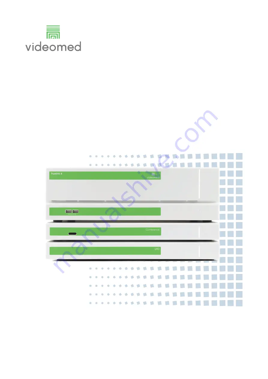
Страница 1: ...Service Manual Truelink 4 Video Management System ENGLISH en US...

Страница 2: ...This page is intentionally blank...

Страница 3: ...the following sales units The manual is provided by VIDEOMED S r l in electronic PDF format on digital media Telephone 39 049 9819113 Fax 39 0434 030689 Document number 80028124 Language ID 030 Versio...

Страница 4: ...link 4 4 80028124_030_A 773701 2021 04 29 VIDEOMED S r l declines any liability for improper use of the system and or for damage caused as a result of operations not covered by the technical documenta...

Страница 5: ...ions and recommendations described in this manual must be complied with It is of particular importance to train the personnel in charge of the machine in regards to its use and for checking compliance...

Страница 6: ...Truelink 4 6 80028124_030_A 773701 2021 04 29 This page is intentionally blank...

Страница 7: ...ypes of analogue signal 19 5 2 1 1 CVBS Composite Video 19 5 2 1 2 YPrPb Component Video 19 5 2 1 3 S Video Separate Video 20 5 2 1 4 VGA and RGB Video Graphics Array 20 5 2 2 Types of digital signal...

Страница 8: ...al Video Interface 57 6 13 2 2 HDMI High Definition Multimedia Interface 57 6 13 2 3 SDI Serial Digital Interface 57 6 13 3 Connect the monitors to Truelink 4 58 7 Internal external cabling 58 7 1 Con...

Страница 9: ...s modifications and repairs are carried out exclusively by the VIDEOMED S r l assistance services only spare parts and accessories authorized by the Manufacturer are used no structural changes to the...

Страница 10: ...l the information and warnings for correct installation in full safety are provided 2 3 Updates VIDEOMED S r l reserves the right to update the service manual at any time with modifications and or tra...

Страница 11: ...onsult the instructions for use before using the equipment Conformity marking symbol of compliance with Regulation EU 2017 745 on Medical Devices Equipotential symbol for potential equalization Protec...

Страница 12: ...he package is fragile and is therefore to be treated with care Indicates the right position to hold the product Keep the package away from rain Maximum number of identical packets that can be stacked...

Страница 13: ...ixels Live preview Real time video preview of a signal source on the operating monitor OSD View on monitor DVI Digital graphic interface an interface for the transmission of video data DICOM Digital I...

Страница 14: ...age to the structure or to the its components WARNING This product can expose you to chemicals including Lead and Di 2 ethylhexyl phthalate DEHP which are known to the State of California to cause can...

Страница 15: ...y with regulatory requirements thanks to the use of components compliant with the Electromagnetic Compatibility Directive suitable connections and installation of filters where required The Truelink 4...

Страница 16: ...and cleaning must be carried out annually to ensure the components remain in good working order and intact Use personal protective equipment for any maintenance and cleaning activities List of protect...

Страница 17: ...nvironmental conditions The Truelink 4 Video Management System has been designed and built to safely operate in the following environmental conditions The environmental conditions relating to the stor...

Страница 18: ...ED S r l 5 1 Standard cabling The standard cabling is provided with 5 2 Types of signal Signals can be analogue digital Image Type of cabling RG 6 CPR certified LSZH shielded coaxial cable Cca s1a d1...

Страница 19: ...h Truelink 4 Best type of signal input for SD signal input 1 RCA connector Cinch 2 BNC connector 3 BNC adapter 4 RCA adapter 1 2 3 4 Name Component Video YPrPb YCbCr Resolution Image rate 1920 1080 60...

Страница 20: ...Use with Truelink 4 Adapter available It can be used as a standard CVBS signal 1 2 x BNC connector 2 1 x DIN S Video connector female connector 2 2 1 Name VGA Video Graphics Array Resolution Image ra...

Страница 21: ...SDI 1920 1080i 1280 720p 3G SDI 1920 1080p Signal type Digital Truelink 4 cable 1 RG 6 Coaxial Conversion Truelink 4 SD SDI PAL SECAM NTSC not natively supported by Truelink 4 In this case conversion...

Страница 22: ...aximum resolution supported 1920 1080 All Truelink 4 DVI connectors are DVI I Dual Link connectors to maximize compatibility However only digital data is used to transfer and display video signals 1 D...

Страница 23: ...les Given the high bandwidth required for communications and the quality of the signals involved the use of high quality cables and connectors is a mandatory requirement The quality of the cables used...

Страница 24: ...plan order specifications is an overview of the installation diagram The diagram shows the connections between the Truelink 4 system its sources and destinations specifying their location and type Th...

Страница 25: ...rom the cable end with a felt tip pen or an adhesive strip depending on the cable definition MAXIMUM LENGTH OF TWISTED PAIR CABLE The Installer Technician must ensure that the actual length of each ca...

Страница 26: ...wires 2 Remove the additional aluminum wire protecting the internal wires up to the point where the outer sheath has been removed 3 Remove the aluminum shield to protect each pair of wires up to the p...

Страница 27: ...Cabling 80028124_030_A 773701 2021 04 29 27 7 Position the end of the connector in such a way that it contains the plugs 8 Use a clamp to crimp the CAT 6 AWG 26 cables Step Image...

Страница 28: ...ct torsions and twists as well as removing any crushed sections or damage occurred during the crimping stage Step Image 1 Proceed by stripping the end of the cable removing the outer sheath protecting...

Страница 29: ...ram RADIO MIC RX MINI PC WORKSTATION EXT USB TX DP USB USB EXT USB 2 x RG58 ANTENNAS CABLES POWER CAT7 to theOR CAT7 internal USB A B 3X RG58 BNC BNC XLR USB 180EPoE 180EPoE EXT USB TX 3 5mm jack MIC...

Страница 30: ...0 6 Videoconference Audio IN Main Conf OUT Stereo Audio Cable Jack 3 5 mm M M 0 6 Videoconference Audio OUT Main Conf IN HDMI cable 2 0 M M 0 5 Videoconference HDMI IN 1 Main HDMI Conference OUT 1 HD...

Страница 31: ...output 1x patch CAT6 utp 5x patch CAT6 sftp 5x patch CAT6 sftp ON AIR plate RJ45 cable junction RJ 45 LED w o o 12V w b b 12V 4x patch RG 6 75Ohm Touchscreen control USB input TCM VISCA Control RoomC...

Страница 32: ...Cabling to connect the modules 6 1 Hardware installation 6 1 1 Rack unit The dimension of the rack are length 800 mm width 600 mm and height 757 mm with a weight 64 kg 1 Holes for cable routing see c...

Страница 33: ...773701 2021 04 29 33 Rack elements Image Junction box with three terminal blocks inside L N PE Principal switch when the switch is on I green light on operating voltage is turned on Medical transform...

Страница 34: ...prepare the connection between the customer s power grid and the Truelink 4 NOTICE DEDICATED MAIN SAFETY SWITCH It have to be placed close to the rack To identify the correct power cord refer to the...

Страница 35: ...installed in a well ventilated room 6 1 5 Aligning and leveling the rack The adjustable feet can be used to compensate for an uneven floor in order to stabilize the rack in a correct and level positi...

Страница 36: ...ows to remove the stand 6 3 2 Preparing the installation of the touch screen Remove the cover before installing the touch screen Proceed as follows to remove the cover Step Image 1 Position touch scre...

Страница 37: ...5 2 Position optional cover 5 on touch screen 1 3 Take 4 screws to fix the touch screen from the accessories for the VESA support arm 4 Insert 2 screws 2 in the designated openings in the cover in the...

Страница 38: ...ds 2 Place 2 fixing screws 2 in projecting parts 10 and 11 of VESA adapter plate 7 and tighten them 3 Turn the remaining 2 screws through the two lower 4 openings in VESA adapter plate 7 and touch scr...

Страница 39: ...or to the relevant DVI connection of the receiver 180 P which receives the signal from the Truelink 4 through the CAT 7 cable The transmission set consists of the following elements 180 P receiver DVI...

Страница 40: ...n a soft surface 2 Undo the 2 screws 3 of the cover of monitor 4 and remove the cover itself 2 3 4 Step Image 1 Unscrew the 2 fixing screws 6 of cover 5 of the support of optional cover 7 and remove c...

Страница 41: ...and push the monitor upwards 2 Position and then fix the 2 fixing screws 8 in the relevant housings 13 on the plate of VESA adapter 10 3 Insert and then tighten 2 more fixing screws 8 in the relevant...

Страница 42: ...evice 1 to the DVI input of the touchscreen inside the cover 7 5 Insert connection cables 6 from the 180 P device to the respective connections on the monitor 6 Insert the 180 P device into cover 7 by...

Страница 43: ...technical data NOTICE Fixing frame 2 must be leveled horizontally to the ceiling or vertically aligned with the wall 2 Slide metal housing 1 of Room Cam 8 onto fixing frame 2 3 Fix metal housing 1 of...

Страница 44: ...ables cover with fixing screw RoomCam Connection kit 1 Identify the best place to install the camera according with few parameters better view not covered by pendants arms availability of space over t...

Страница 45: ...r the power supply low voltage cable 4 Place the camera under the ceiling and fix it with the special screw included on the RoomCam connection kit through the hole 1 5 Connect the 180E PoE to the DVI...

Страница 46: ...Components installation 46 80028124_030_A 773701 2021 04 29 6 Place the cables cover and screw it to the Special Counterplate using the long screw supplied with the kit Step Image...

Страница 47: ...iling panel where On Air lamp will be installed 2 Make 3 holes aligned and approx 15 cm from the wall edge 3 Remove the upper interface plate by unscrewing the 2 side screws and slide in the hexagonal...

Страница 48: ...r the ceiling with washers and nuts 5 Connect power to the cable connected to the Truelink 4 Main Unit on the On Air port following the diagram on the side Step Image ON AIR LAMP TL4 ON AIR ctrl port...

Страница 49: ...1 Use the drilling template supplied to mark the size of the speaker hole on the ceiling The hole in the false ceiling must comply with the dimensions of sealing ring 1 of reinforcement frame 4 2 Cut...

Страница 50: ...evice on the right side again and close it 9 Screw cable gland 4 and cover audio cable 6 with adhesive tape so that the cable is fixed by the cable clamp Audio cable 6 must have some clearance in rela...

Страница 51: ...ponents installation 80028124_030_A 773701 2021 04 29 51 12 Tighten the 2 fixing screws 8 until speakers press against the ceiling or against the reinforcement frame 13 Position cover 9 Step Image 7 8...

Страница 52: ...roceed as follows to install the receiver Step Image 1 Screw short bracket 1 on the left side and long bracket 3 on the right side of the receiver 2 with 3 self threading screws 6 The holes in the rec...

Страница 53: ...nic circuit board on the base and make sure that the 3 holes for the fixing screws are in the right position coinciding with the supports on the base and that hole A is on the same side of the flat ar...

Страница 54: ...of the TCM to create the right access for the cables 2 Side access TCM positioned on under a surface and the cable will come from the side e g if it will be placed under the shelf of a pendant Make a...

Страница 55: ...ing with a RJ45 plug on both sides TC1 cable 2 Connect the TCM to the emergency button with a 2x1 mm cable without plugs TC2 as the TCM electronic circuit board and the button are fitted with special...

Страница 56: ...he Trumpf Light Control TLC Proceed as follows to install the TLC Step Image 1 Check that the OPL interface converter is connected to the Truelink 4 main unit through the dedicated Lights CTRL port 2...

Страница 57: ...oE adapter and connect it to the DVI IN connector on the main unit 3 Connect another twisted pair cable from the DVI OUT 3 connector located on the back of interface module 1 to the DVI DV 4 connector...

Страница 58: ...e active speakers Proceed as follows to connect the speakers 1 Connect the speakers with a stereo cable with a 3 5 mm jack to the output of the stereo section on the audio unit 7 1 2 Connecting the pa...

Страница 59: ...s to prevent interference and faulty transmissions Proceed as follows to adjust the frequencies Step Image 1 Slide down the door locking flaps 2 With the flaps lowered open the battery compartment doo...

Страница 60: ...he Main unit The Main unit of the Truelink 4 Video Management System is positioned inside the Rack with upon request the two optional units called Conference and UHD or UHD Plus Refer to the image bel...

Страница 61: ...system will prompt you to enter a username and password Contact VIDEOMED S r l to request your login details Proceed as follows to access the configuration system directly from the GUI user interface...

Страница 62: ...ce signals previously installed and cabled by the Technician Proceed as follows to configure the SOURCES section 1 2 4 3 Pos Element Description 1 MAIN MENU List of configurable sections 2 SECONDARY M...

Страница 63: ...list open the details of the source to be moved and assign the desired position by modifying the Position field value NOTICE It is not possible to connect several sources to the same port Each source...

Страница 64: ...d to add modify or remove monitor signals previously installed and cabled by the technician Proceed as follows to configure the MONITORS section Step Image 1 Press to enable or disable the option It i...

Страница 65: ...the technician 8 1 2 1 Options This subsection is used to activate the Use touchscreen as additional monitor option which allows you to use the touchscreen as an additional destination displaying it...

Страница 66: ...stomize the configuration of the video registration for the Truelink 4 system 4 HARDWARE STREAMING Section where you can customize the streaming configuration of the Truelink 4 system 5 VIDEOCONFERENC...

Страница 67: ...sts of three macro areas listed below The details of each section are reported in the following pages 3 1 2 Pos Element 1 GENERAL 2 GENERAL Touchless link connection to the Therapixel Fluid system 3 G...

Страница 68: ...ent System is installed Proceed as follows to edit the field The Hospital Structure name field is used to customize the name of the hospital where the Truelink 4 Video Management System is installed P...

Страница 69: ...le field is used to set the language employed to view the graphic interface of the Truelink 4 Video Management System Proceed as follows to edit the field Step Image 1 Select the desired language to v...

Страница 70: ...ent System Proceed as follows to edit the field Step Image 1 Select to change the date and time This opens the configuration window 2 Activate the change and customize the date and time format for the...

Страница 71: ...e configuration window 2 Press to enable disable the Pin Lock feature 3 With the Pin Lock feature enabled press the Pin editable field to change the pin to access the touch screen features 4 With the...

Страница 72: ...1 04 29 5 With the Pin Lock feature enabled press to enable the monitor lock feature upon system startup 6 After editing the Pin Lock settings press to confirm the changes 7 Press the key at the top o...

Страница 73: ...o edit the field Step Image 1 Select to edit the IP address the touchless system is associated with 2 Select to edit the Room ID of the specific touchless system 3 Tick off the Route to touchless moni...

Страница 74: ...the system NOTICE The parameters for the live video transmitted from the sources to the monitors are not modified in any way Proceed as follows to edit the field Step Image 1 Press the editable Scale...

Страница 75: ...the changes made Step Image Step Image 1 Press the Static Routes editable field This opens the configuration window 2 Select Target to indicate the desired transmission output This opens the window t...

Страница 76: ...Mode field is used to enable disable the full screen feature of the input signals on the control touchscreen Proceed as follows to edit the field Step Image 1 Press to enable disable the full screen f...

Страница 77: ...r exiting the mute mode 2 Change the Default volume level of the audio channels 3 Change the Boost volume level of the microphone ports 4 Press to enable the changes to the Audio automation section Th...

Страница 78: ...sable the type of audio inputs Selecting the label next to the activation deactivation symbol it is possible to change it 4 Press to enable or disable the Talkback feature during a video conference Se...

Страница 79: ...nable or disable the view of the recording status By enabling the feature the system informs the operator through dynamic indications about the registration status 3 Press to enable or disable the aut...

Страница 80: ...ble disable the editing of videos already saved and to take snapshots of them Proceed as follows to edit the field 5 Press the key at the top of the menu bar to save the changes made Step Image Step I...

Страница 81: ...ort destination This opens the configuration window 2 Enter the name of the new destination the type PACS USB LAN the server address ONLY if LAN has been selected 3 Tick off the Create folder if not e...

Страница 82: ...Configuring Truelink 4 82 80028124_030_A 773701 2021 04 29 6 Press to confirm or to cancel the changes 7 Press the key at the top of the menu bar to save the changes made Step Image...

Страница 83: ...ion Step Image 1 Press the Patient ID editable field This opens the configuration window 2 Select the patient fields that must be filled out 3 Press to enable or disable the Emergency Patient feature...

Страница 84: ...eaming is an optional feature that can be activated with a license 2 a Select the Default internal path Do not change the login details unless they have been previously changed b Select the network pa...

Страница 85: ...the configuration of the streamer s network parameters 5 Press the Open web interface editable field The streaming link window opens automatically on the browser 6 Press the Manage stream settings edi...

Страница 86: ...it to enable its control Press to enable or disable the display of the proprietary UI the Video Conference module For maintenance only By default the UI is hidden 3 Press the Fullscreen editable field...

Страница 87: ...701 2021 04 29 87 5 Press the editable field to select the maximum number of recent calls to be displayed 6 Press the Clear list field to delete the list of calls 7 Press the key at the top of the men...

Страница 88: ...our contacts Proceed as follows to edit the section Step Image 1 Press to add a new contact This opens the configuration window 2 Enter the name of the new contact the IP address of the new contact 3...

Страница 89: ...an optional feature that can be activated with a license 2 Press to add a new lamp model This opens the configuration window 3 Select the lamp type and the relative address also indicating the specifi...

Страница 90: ...e the OR Tables feature OR Tables is an optional feature that can be activated with a license 2 Enter operating table name infrared code of the operating table operating table model 3 Press to enable...

Страница 91: ...o the Truelink 4 Video Management System Proceed as follows to edit the field Step Image 1 Press to enable or disable the Remote Devices feature Remote Devices is an optional feature that can be activ...

Страница 92: ...mote control of the Operamed TCP only if present Proceed as follows to edit the section Step Image 1 Press the editable Configure Connection setting field This opens the configuration window 2 Enter t...

Страница 93: ...Configuring Truelink 4 80028124_030_A 773701 2021 04 29 93 6 Press to confirm or to cancel the changes 7 Press the key at the top of the menu bar to save the changes made Step Image...

Страница 94: ...oceed as follows to edit the section Step Image 1 Select a previously saved configuration and apply it to the Truelink 4 Video Management System Every time you save a setting in the Sources Monitors o...

Страница 95: ...as follows to edit the section Step Image 1 Press to add a new Backup file This opens the configuration window 2 Select whether to specify the name of the new backup Specify a label or leave the date...

Страница 96: ...ssociated with a specific system You cannot use a license already associated with a system on a different system Step Image 1 Click the installed license name to view the details of the installed comp...

Страница 97: ...cannot use a license already associated with a system on a different system Step Image 1 Insert a USB pen drive containing the new license to be installed 2 Press to install a new license This opens...

Страница 98: ...1 6 Advanced menu The advanced menu is divided as follows The details of each section are reported in the following pages 1 RESET 2 IMPORT 3 EXPORT 4 CREATE CUSTOMER SERVICE PACKAGE 5 ABOUT 6 LOGOUT T...

Страница 99: ...8124_030_A 773701 2021 04 29 99 8 1 6 1 Reset The Reset feature is used to upload again the last settings saved in the configuration system Proceed as follows to Reset Step Image 1 Press to upload the...

Страница 100: ...Video Management System Proceed as follows to perform Imports Exports Step Image 1 Press to go to the export feature This opens the configuration window 2 Press to export the settings created The set...

Страница 101: ...ered in the imported settings if you import settings in a different operating room 4 Press to choose the file to import This opens the resource management window 5 Press to export the settings created...

Страница 102: ...end it to the service authorized of VIDEOMED S r l if various malfunctions or bugs have been found to have a complete diagnostic analysis of the settings carried out Proceed as follows to create and s...

Страница 103: ...ure is used to access the general information menus of the Truelink 4 Video Management System Proceed as follows to go to the About feature 4 Press to download the package and send it to service cente...

Страница 104: ...on SOFTWARE MODULES displays the modules installed in the Truelink 4 Video Management System By pressing each module you can view the various details such as version license and Manufacturer s site 4...

Страница 105: ...ink 4 80028124_030_A 773701 2021 04 29 105 8 1 7 1 Logout The Logout feature lets the user disconnect from the Truelink 4 configuration system Proceed as follows to Logout Step Image 1 Press to log ou...

Страница 106: ...ck PROKEYS MEDIGENIC all in one PC on rack PROKEYS MEDIGENIC all in one PC on rack PROKEYS MEDIGENIC presence size active IP GW SM enabled pending received provided pending n a VDM 8602 pag 1 6 Instal...

Страница 107: ...yed on touchscreen Send the signal to each one of the monitors installed and check if a stable image is displayed for at least 1 minute repeat the same procedure with a 1920x1200 p60 source 2 Repeat t...

Страница 108: ...ons until the mechanical limit 3 Memorize 3 preset positions and recall them CHECK LIST UHD Unit MECHANICAL STATUS AND INTERNAL COMPONENTS 1 Verify parts integrity cleaning status and closure systems...

Страница 109: ...Annex I Installation report 80028124_030_A 773701 2021 04 29 109 VDM 8602 pag 4 6 Installation report rev 00 23 03 2020 CABLING PLAN...

Страница 110: ...DVI 7 DVI 7 DVI 8 DVI 8 DVI 9 DVI 9 DVI 10 DVI 10 DVI 11 HDMI 1 DVI 12 HDMI 2 DVI 13 HDMI 3 DVI 14 HDMI 4 SDI 1 HDMI 5 SDI 2 CVBS 1 CTRL 1 CVBS 2 CTRL 2 HDMI 1 CTRL 3 HDMI 2 CTRL 4 HDMI 3 CTRL 5 HDMI...

Страница 111: ...8124_030_A 773701 2021 04 29 111 ORIGINATED BY APPROVED BY VDM 8602 pag 6 6 Installation report rev 00 23 03 2020 ____ ____ _______ ____ ____ _______ Signature Signature FINAL APPROVAL ____ ____ _____...

Страница 112: ...Annex I Installation report 112 80028124_030_A 773701 2021 04 29 This page is intentionally blank...

Страница 113: ...This page is intentionally blank...

Страница 114: ...80028124_030_A 773701 2021 04 29...

Отзывы: