background image

OneExpert DSL User's Guide

22052280, Rev. 015

April 2019

Chapter 

2  Quick Tour

39

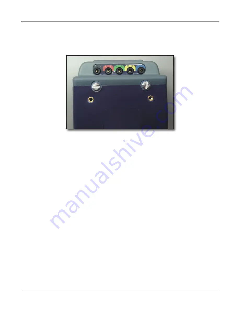
Exploring the ONX-580 / ONX-580P top panel 

The upper area of the back panel of the ONX-580 / ONX-580P module houses the connectors 

for Copper or G.fast/xDSL testing.

These connectors are not provided on the ONX-580A. 
The copper connectors are used for: 

•  Multimeter 

– AC volts 
– DC volts 

•  TDR 
•  Opens (distance) and capacitance 
•  Balance 
•  Load coil detect 
•  POTS 
•  Spectral
•  RFL 
•  Noise 
•  Impulse Noise 
•  RX Tones

Содержание OneExpert DSL ONX-580

Страница 1: ...OneExpert DSL User s Guide ...

Страница 2: ...and logos are registered trademarks owned by Bluetooth SIG Inc and any use of such marks by VIAVI is under license All other trademarks and registered trademarks are the property of their respective owners Copyright release Reproduction and distribution of this guide is authorized for US Government purposes only Ordering information This guide is a product of VIAVI Technical Publications Departmen...

Страница 3: ...ications be made to the equipment unless the changes or modifications are expressly approved by VIAVI This device complies with Part 15 of the FCC Rules Operation is subject to the following two conditions 1 This device may not cause harmful interference and 2 This device must accept any interference received including interference that may cause undesired operation If this equipment does cause ha...

Страница 4: ...dustry Canada limites établies pour un environnement non contrôlé This Class A digital apparatus complies with Canadian ICES 003 Cet appareil numérique de la classe A est conforme à la norme NMB 003 du Canada CAUTION This transmitter must not be co located or operating in conjunction with any other antenna or transmitter Cet émetteur ne doit pas être co localisées ou opérant en conjonction avec un...

Страница 5: ...cle 10 8 a and 10 8 b of the RED the OneExpert CATV instruments for sale in the EU operates in the 5 205 MHz frequency range at a maximum RF transmit power of 15dBm Please contact us for more information VIAVI Solutions Network Service Enablement 6001 America Center Drive San Jose CA 95002 California Proposition 65 California Proposition 65 officially known as the Safe Drinking Water and Toxic Enf...

Страница 6: ...OneExpert DSL User s Guide 22052280 Rev 015 April 2019 vi ...

Страница 7: ...nitions 20 Chapter 1 Introduction 21 About the OneExpert DSL 22 Available mainframes 23 Available test modules 23 Software options 24 Additional resources 25 Features and capabilities 26 What ships with the OneExpert DSL 28 Preparation for use 28 Attaching or removing a test module 29 Removing a test module 29 Attaching a test module 30 Chapter 2 Quick Tour 31 Exploring the front panel 32 Status I...

Страница 8: ...ering data 44 Creating or removing a shortcut 44 Chapter 3 Utilities 45 Accessing system utilities 46 Displaying the System Settings menu 46 Displaying the Tray menu 47 Setting up your instrument 48 Configuring international settings 48 Setting the date and time 49 Set the time 49 Set the date 49 Specify the date format 49 Specify the time format 49 Change the time zone 49 Control Time Synchroniza...

Страница 9: ...trataSync 62 Creating custom OneCheck icons 64 OneCheck Copper DSL Fiber Ethernet Profile Editor 65 Generating reports 66 What s new 66 Saving a report 67 Viewing a report 68 About custom report fields 69 Enforcing report field entry 69 Specifying custom report fields 69 To specify custom report fields 70 Capturing a screen shot 70 To capture a screen shot 70 To capture the tray menu or a popup me...

Страница 10: ...cting to a single twisted pair 91 Connecting to bonded twisted pairs 91 Connecting to a single pair at the NID demarc 91 Connecting to bonded pairs at the NID demarc 92 Testing the physical layer 92 Testing line quality 92 Terminating the loop SELT 93 Running a OneCheck DSL test 93 OneCheck DSL Editor 95 Testing the data layer 96 After running the test 96 Chapter 5 Data Testing 97 About Data Tests...

Страница 11: ...deo streams 120 Terminate mode 120 QoS Expert 121 VoIP Testing 121 Accessing the VoIP application 122 Specifying test settings 122 Connecting to the line 125 Placing and receiving calls 125 Placing a call 125 Receiving a call 126 Answering calls automatically 126 Browsing the web 127 Accessing the web browser 127 Navigating the browser 127 Opening a web page 127 Adding bookmarks 128 Exiting the br...

Страница 12: ...i Testing 149 About the WiFi tests 150 To access the WiFi tests 150 Scanning for WiFi networks 151 Running Receiver Diagnostics 151 Verifying IP connectivity 152 Providing WiFi hotspot access 152 WiFi Coverage Expert 153 WiFi Troubleshooting using WiFi Coverage Expert 154 Audible Finders 155 Site Assessment 155 Managing WiFi Advisor Devices 156 Registering and unregistering devices 156 To register...

Страница 13: ...85 Measuring the distance to a short 186 Measuring resistive balance 187 Measuring opens 187 Measuring current 190 Locating faults using the TDR 191 Running a OneCheck TDR test 193 Running a CrossTalk TDR test 194 Measuring balance 195 Measuring PI power influence noise and balance 195 Detecting load coils 196 Testing voice service and caller ID 196 Locating faults using RFL 198 Single Pair RFL te...

Страница 14: ... OneCheck POTS Closeout 220 Test default configurations and thresholds 221 OneCheck Coax 222 Routing the cables through the glove 223 Chapter 14 Fiber Testing 225 About fiber testing 226 OneCheck Fiber 227 Running a OneCheck Fiber test 228 OneCheck Fiber Editor 229 Fiber Inspection 230 Optical Power Test 230 OTDR Test 231 Saving the profile and launching the test 231 Fiber Certification 232 SmartO...

Страница 15: ...Results 255 File Transfer results 256 TrueSpeed results 256 VoIP results 256 Summary 256 QoS 256 MOS 257 Network results 257 Call Information results 258 Video results 258 Summary 259 QoS results 260 Loss results 260 Packet statistics 261 Stream Rates 261 Stream TS statistics 261 PID results 262 HPNA results 263 Node list 263 Node details 263 Network Test 264 SmartID results 266 Test Summary 266 D...

Страница 16: ...se 272 RX and TX Tones 272 WiFi Advisor results 273 BSSID results 273 Channel results 273 RSSI view 273 Utilization graph 273 Noise graph 273 Channel Score 273 Best Channels 274 Spectral results 274 Chapter 17 Appendix 275 Cleaning the instrument 276 Resolving problems 276 General testing 276 Copper testing 276 Copper testing 276 Data testing 277 WiFi Advisor 278 Getting Technical Assistance 279 A...

Страница 17: ...es a complete description of the VIAVI warranty services and repair information Assumptions This guide is intended for novice intermediate and experienced users who want to use the OneExpert DSL effectively and efficiently We are assuming that you have basic computer and mouse track ball experience and are familiar with basic telecommunication concepts and terminology Technical Assistance If you r...

Страница 18: ...ed in the following tables Description Example User interface actions On the Status bar press Start Buttons or switches that you press on a unit Press the ON switch Code and output messages All results okay Text you must type exactly as shown Type a set exe in the dialog box Variables Type the new hostname Book references Refer to Newton s Telecom Dictionary A vertical bar means or only one option...

Страница 19: ...ERT message See Safety Definitions on page 20 for more information This symbol represents an alert It indicates that there is an action that must be performed in order to protect equipment and data or to avoid software damage and service interruption This symbol represents hazardous voltages It may be associated with either a DANGER WARNING CAUTION or ALERT message See Safety Definitions on page 2...

Страница 20: ... will result in death or serious injury It may be associated with either a general hazard high voltage or other symbol WARNING Indicates a potentially hazardous situation that if not avoided could result in death or serious injury It may be associated with either a general hazard high voltage or other symbol CAUTION Indicates a potentially hazardous situation that if not avoided could result in mi...

Страница 21: ... provides a general description of the OneExpert DSL Topics discussed include the following About the OneExpert DSL on page 22 Features and capabilities on page 26 What ships with the OneExpert DSL on page 28 Preparation for use on page 28 Attaching or removing a test module on page 29 ...

Страница 22: ... the home supporting wiring inside of the home and the proper operation of delivered services The OneExpert is designed to support DSL copper services and home networks Each OneExpert instrument provides the controls and display needed for measurement analysis and the instrument s modularity will ensure years of use The combination of its multi touch user interface and unique Viavi OneCheck automa...

Страница 23: ... modules and part numbers NOTE For additional information about OneExpert DSL options and services contact your local VIAVI representative or visit www viavisolutions com Part Number Description ONX580 BDCM DSL BONDED OneExpert Broadcom 63168 bonded ready test module ONX BDCM DSL ANXAB OneExpert Broadcom 63168 VDSL ADSL2 ANX A B test module ONX BDCM GFAST OneExpert Broadcom 63138 VDSL ADSL2 ANX A ...

Страница 24: ...ng over two pairs ONX580 GFAST Provides the ability to perform xDSL testing over G fast lines using Broadcom chipset Requires a ONX BDCM GFAST or ONX TM GFAST test module ONX580 GFAST SCKIPIO Provides the ability to perform xDSL testing over G fast lines using Sckipio chipset Requires a ONX TM GFAST test module ONX580 HPNA Allows testing of HPNA networks ONX580 IPVIDEO Allows testing of IP Video s...

Страница 25: ... option ONX580 MOBILE 001 Provides the mobile option ONX SPEEDCHECK Allows Speed Check testing ONX SMARTID MOCA Allows SmartID MoCA testing ONX580 COPPER EXPERT Provides the Copper Expert testing option ONX580 DSL HELPER Provides the DSL Helper option Software options continued Additional resources Providers can also improve their work processes data flow and OPEX by expanding field tester usage i...

Страница 26: ...DSL services Packet statistics and analysis ADSL2 VDSL2 testing including bonded and vectored pairs requires supporting test module Single ended Loop Testing SELT DSL G fast PHY firmware on modem updates HPNA testing monitor and test modes Home Wiring testing including Wire Map Tone Trace and Hub Flash Port Discovery and a Ping Tool WiFi testing including WiFi Scan and WiFi Access Point testing Wi...

Страница 27: ...tomates field tests and simplifies copper results RFL K Test OneCheck Good Pair test OneCheck Copper with UltraFed test Spectral testing Noise testing Impulse Noise testing Wideband Sweep Loss with UltraFED and Wideband Balance Sweep ONX 580A functions without Copper board to reduce cost Customizable work order integration contact your sales representative for information Sending multiple work ord...

Страница 28: ...rt for damage If the instrument is damaged put it back in box and contact Viavi customer service see Technical Assistance on page 17 If undamaged save the box and packing materials in case you need to ship the instrument in the future Remove the protective film from the LCD This film is in place to protect the LCD during shipment Use the tab in the lower right corner to easily remove the film Befo...

Страница 29: ... NOTE Before removing or attaching a test module the instrument must be powered down and all cables must be disconnected CAUTION STATIC SENSITIVE Static shock may damage the instrument Observe anti static precautions when handling the module Removing a test module Modules can be removed by loosening the four screws on the back of the base unit 1 Loosen the four screws using a screwdriver or a coin...

Страница 30: ... on the module line up with the connectors on the back of the base unit If correctly positioned the four screws also line up 2 Gently push the module to mate the connectors 3 Tighten the four screws Tighten by hand until the housing and screw contact each other Turn the fastener one complete turn using a screwdriver or a coin The module is connected ...

Страница 31: ... status indicators connectors and graphical user interface Topics discussed include the following Exploring the front panel on page 32 Exploring the bottom panel on page 35 Exploring the right side panel on page 36 Exploring the ONX 580 ONX 580P top panel on page 39 Navigating the user interface on page 41 ...

Страница 32: ...d indicators on the front panel are used to operate the OneExpert DSL set up tests and view data The following sections describe each of the controls and indicators on the front panel Status indicators High sensitivity touchscreen display Softkeys Shortcut buttons Arrows OK buttons Back Home and Tray buttons Power button ...

Страница 33: ...s an IP address has been acquired Blinking amber indicates a timeout the unit was unable to acquire an IP address If the Frame indicator is not illuminated the network is not active either the unit is not connected or it is logged off NOTE The Sync and Network indicators alternately blink green when in sleep mode power saving mode Error Solid red indicates error and alarm conditions Batt A multi c...

Страница 34: ...sociated with each key Arrow buttons Use the arrow buttons to navigate through menu selections OK button Use the OK button to accept a changed setting or to proceed to the next menu System buttons The Back Home and Tray buttons are found under the arrow buttons Back Cancel Exit a menu or to go back to the previous menu Home Return to the main home screen Tray Displays the Tray menu to save test re...

Страница 35: ...rger connector is a multi color indicator that shows the charge status Solid green Indicates charging is complete Slow flashing red Indicates the battery charge is critically low less than 10 Fast flashing red Indicates the charging was suspended due to a fault and user intervention is necessary for example the wrong charger is attached Solid red Indicates the charging was suspended due to overhea...

Страница 36: ...trument under a rubber flap provides the ports required to connect your OneExpert DSL to the line under test When the connectors are not being used close the rubber flap to keep out dust and rain ONX 580 and ONX 580P connector panel xDSL G fast connector xDSL G fast connector ONX 580A connector panel NOTE POTS and wiring ports are not provided on the ONX 580A module ...

Страница 37: ... testing Network connectors Two Ethernet Network ports are used to connect to Ethernet networks to allow testing such as hub flash port discovery and ping synchronize with StrataSync upgrade software and remotely connect to the OneExpert RJ45 Wiring connector The RJ45 wiring connector is used on the ONX 580 ONX 580P for RJ45 wire ID RJ45 toning Wire mapping to smart remote CAUTION DAMAGE TO INSTRU...

Страница 38: ...amage to the connector Rings The D rings on the corners of the instrument can be used to attach a carry strap WARNING ELECTRICAL SHOCK Electrical shock may result in serious injury or death Use care when connecting to telecommunications circuits to be sure that you do not come in contact with exposed conductors or power mains Connect TNV signals to TNV ports only NOTE ELECTROSTATIC DISCHARGE IMMUN...

Страница 39: ... area of the back panel of the ONX 580 ONX 580P module houses the connectors for Copper or G fast xDSL testing These connectors are not provided on the ONX 580A The copper connectors are used for Multimeter AC volts DC volts TDR Opens distance and capacitance Balance Load coil detect POTS Spectral RFL Noise Impulse Noise RX Tones ...

Страница 40: ...ath Use care when connecting to telecommunications circuits to be sure that you do not come in contact with exposed conductors or power mains Connect TNV signals to TNV ports only CAUTION INSTRUMENT DAMAGE Connecting to circuits with voltage higher than 300V compared to ground may damage the internal components Connect only to circuits with less than 300V ...

Страница 41: ... a mobile device such as an iPad or similar Android device where you swipe to go to the next page or zoom in out by pinching or opening your fingers Using the interface you can view test results set up the OneExpert and configure test parameters When you power up the OneExpert the Home screen appears The Home screen indicates the options enabled on your instrument and may vary depending on the mod...

Страница 42: ...ain menu is a collapsible menu You can expand each of the collapsible menu items by doing either of the following options Press the triangle on the right Use the arrow buttons to highlight the desired menu item Copper is highlighted below and then press OK The triangle points down to show the menu is expanded Selecting a menu option After you expand a collapsible menu you can select a specific opt...

Страница 43: ...ltiMeter you can return to the home menu by pressing the home icon in the upper left corner of the application s screen The application will keep running and the icon on the home screen will be highlighted showing that it s active You can either leave it running or shut it down by pressing the Back button in the upper left corner of the highlighted icon ...

Страница 44: ... keypad the up arrow is the shift button On the numeric keypad the second button 1 2 allows you to move among multiple numeric screens The left pointing arrow with the X in it is the backspace button 4 Press the enter return button on the onscreen keypad or press OK The data is entered and stored Creating or removing a shortcut If you have a test or function that you use frequently you can make it...

Страница 45: ...ude the following Accessing system utilities on page 46 Setting up your instrument on page 48 Restoring factory defaults on page 52 Establishing network connections on page 53 Updating the instrument s firmware on page 60 Synchronizing to the StrataSync server on page 62 Creating custom OneCheck icons on page 64 OneCheck Copper DSL Fiber Ethernet Profile Editor on page 65 Generating reports on pag...

Страница 46: ...ng the System Settings menu Using the items provided on the System Settings menu you can turn on remote operation via VNC Viewer change screen and power settings control the volume view hardware and software versions view options purchased with your meter and complete USB software updates 1 From the Main menu press the System menu item 2 Press the System Settings icon The System Settings menu appe...

Страница 47: ... can specify settings required for network WiFi and Bluetooth connectivity control the volume on your instrument and manage reports You can also take screenshots of the user interface and review a PDF of this guide on your instrument To bring up the Tray menu do either of the following Press the Tray button Swipe downward from the top of the screen ...

Страница 48: ...ngs will be retained when you turn your instrument off 1 Go to the System Settings menu then select International Settings The International Settings menu appears 2 Optional Select Country to select a preset country Selecting a specific country will automatically change the settings as appropriate for that country For example selecting France will automatically set the language to Francais the mea...

Страница 49: ...and year 3 Select the day on the calendar 4 Press Set Specify the date format 1 Press Date Format 2 Select MM DD YYYY or DD MM YYYY Specify the time format 1 Press Time Format 2 Select 12 Hour or 24 Hour Change the time zone 1 Press Time Zone 2 Select the time zone 3 If Daylight Savings Time DST is used in your area press the DST Used checkbox to enable DST A check mark will appear indicating that...

Страница 50: ...ime during which no keys are pressed and no line activity takes place So if you set the Power Off Delay to 5 minutes and then begin a 15 minute test the unit will not power down during the test because there is activity on the line as a result of the test NOTE The OneExpert will not automatically power down when connected to the AC adapter Go to the System Settings menu then select Screen Power Ma...

Страница 51: ...will be saved to the location and or device specified Automatically saving DSL test results You can set up your instrument to automatically save DSL and One Check DSL test results including graphical results in an XML format on the instrument The XML result output will then be sent automatically the next time you synchronize to the StrataSync server If you enable this function the instrument will ...

Страница 52: ...ame workgroup company email address and other information 3 Press the Back Cancel button to save and exit the menu The user information is specified NOTE Restoring factory defaults resets test application settings and system settings such as brightness contrast and volume and powers down the unit Powering off and rebooting the unit Besides pressing and holding the power button to turn off your ONX...

Страница 53: ...erface remotely Enabling network connectivity Before you establish a connection to an Ethernet or WiFi network you must enable network connectivity on your instrument 1 Go to the Tray menu 2 Press the Network icon The icon will be green when connectivity is enabled Network connectivity is enabled NOTE You cannot use Bluetooth when the ONX is acting as a WiFi Access Point letting other devices conn...

Страница 54: ...or located on the side panel Connect the other end of the Ethernet cable to the LAN 2 Verify that network connectivity is enabled in the previous section 3 Go to the System menu then press Network The System Network menu appears 4 Select the Ethernet button at the bottom of the menu Items appear that allow you to specify settings that are required to connect to the LAN 5 Select Network Mode and th...

Страница 55: ...y the following settings IPv6 Address Mode DHCPv6 DHCPv6 Request Type Address Specify the address Prefix Specify the prefix Stateless IPv6 DNS Address Mode DHCPv6 No additional settings to specify Manual Enter the IPv6 DNS Server address Static IPv6 Global Address Enter the instrument s IPv6 address to access the global network IPv6 Local Address Manual Enter the IPv6 Local Address Automatic The a...

Страница 56: ... 56 IPv4 IPv6 Dual Stack Address Modes Static See the IPv4 Address Mode in this section Stateless See the IPv6 Address Mode in this section 7 Display the Tray menu and then press Network to establish the connection The instrument establishes an Ethernet connection to the LAN ...

Страница 57: ... at the bottom of the menu Your instrument immediately scans for WiFi networks and lists each network as an item 4 Press Add Network The Add WiFi Network menu appears 5 Specify the following settings SSID The SSID Service Set Identifier of the WiFi network Password The password required to authenticate to the network A password is not required if Key Management is set to None Key Management Open W...

Страница 58: ...Range A profile for the network has been saved on your instrument and a connection can be established to the instrument Saved Out of Range A profile for the network has been saved on your instrument but the network is out of range and therefore a connection cannot be established Incompatible A connection cannot be established to a network Connected The instrument has already established a connecti...

Страница 59: ...to the System Settings menu then select Bluetooth The Bluetooth Settings menu appears 2 Press the box next to Enabled A checkmark appears 3 Press Scan for devices The instrument scans for Bluetooth devices then lists the devices on the menu 4 Select the device to connect to If the instrument successfully authenticates to the device a message appears indicating that pairing was successful If the in...

Страница 60: ...wnloading the firmware Updating the firmware from a USB drive Connect the OneExpert DSL to the AC charger adapter to ensure an uninterrupted supply of power during the update Once your ONX has been updated you have the option to reboot it Viewing hardware software versions and options The following procedure describes how to view the status of available options and the hardware and software versio...

Страница 61: ...n the previous sections If you received the option file by email instead of a USB drive save the option file to a USB drive 2 Insert the USB drive into the OneExpert 3 From the main menu press the System menu item The collapsible menu opens 4 Select USB File Browser 5 Highlight the option file on the USB drive 6 Select File Option and then Copy to Internal The file is copied to the internal file b...

Страница 62: ...lates To obtain the latest configuration settings software options and updates work orders and ownership registration information the OneExpert can synchronize with a VIAVI server via the internet The synchronization also stores any user files saved on the unit to the StrataSync server This procedure should be undertaken immediately upon receipt of the unit and on a regular daily basis thereafter ...

Страница 63: ...e unit s user settings name user technician and ID The last calibration date of the copper board if applicable this is not provided for the ONX 580A which does not have a copper board Software update milestones includes status and warnings if applicable If the configuration information contained on the server is newer than that on the unit the server will be considered to be the most up to date Th...

Страница 64: ... OneCheck icons 1 Create an image and place it in the root directory of a USB drive The image must be in the PNG format and have no spaces in the name 2 Load up a OneCheck profile by selecting an icon under OneCheck Copper DSL Fiber or Ethernet 3 Insert the USB drive 4 Press Icon to see the available icons 5 Select an icon press Back and press Save to save your changes and exit NOTE If StrataSync ...

Страница 65: ...h of these tests for more information 4 To edit the existing profiles that are listed on the screen including the new ones you just created press the Profile button 5 In the opened Profile menu you can set the following configurations Set Home Screen Label Sets the name of the test Set Home Screen Icon Sets the image next to the test name To set it you need to have the file named screen001 png on ...

Страница 66: ...pp on page 241 New JSON and XML report formats The following tests support the new VIAVI Common Data Model CDM format OneCheck Copper Fiber DSL Ethernet Ethernet DSL and DSL bonded Generating reports The Save Report icon provided on the Tray menu allows you to create reports based on the configuration settings and test results for the currently active test Save Profiles Packages to USB Saves all O...

Страница 67: ...test followed by a three digit number that increments with each file saved for example cablecheck001 or DSL002 3 Specify the format PDF XML HTML or JSON 4 If you want to include custom fields in the report enable then specify values for the fields 5 Do one of the following To view the report immediately press Save and View To save the report without viewing it press Save The current test results c...

Страница 68: ...w saved reports on the LCD of your instrument 1 Access the Tray menu and then press View Report A View Report screen appears showing all of the saved reports 2 Select a report to view The report appears on the screen NOTE If the View Report icon is disabled gray there are no reports saved on your instrument ...

Страница 69: ...DF or HTML report output Enforcing report field entry You can set up your instrument to require that custom report fields be populated before generating and saving a report 1 Go to the System Settings menu then select Enforce Report Fields Data The Enforce Report Fields Settings menu appears 2 Press the box next to Enforce Report Field Entry A checkmark appears 3 Press the Back Cancel button to sa...

Страница 70: ...select the field that you want to include in your report The field is selected an displayed on the Customer Information menu with a check mark indicating that it has been selected for the report Select the field to display a data entry screen Enter a value for the field then press OK The value that you specified appears directly under the field name on the Customer Information menu You have specif...

Страница 71: ...Utilities 71 Viewing your work orders The WorkFlow Manager icon provided on the Tray menu allows you to see all your current work orders Tests specified within the work orders can be launched from here Select a work order to view it and then choose the test to run it ...

Страница 72: ...onnected USB flash drive press the USB File Browser button The File Browser menu appears listing all folders or files Selecting files or folders 1 Go to the file browser 2 Use the up and down arrow buttons to move among folders or files to see the contents of a folder press the folder 3 Do one of the following To select a single file or folder press the checkbox to the left of the file or folder T...

Страница 73: ...ing files using FTP HTTP 1 Go to the file browser 2 Select the file or folder 3 Press the File Options system key and then select Upload FTP HTTP The upload settings appear 4 Specify the upload URL username and password 5 Press Apply The upload starts When the upload finishes a message appears stating that the selected files were uploaded Press OK to close the message Managing files with StrataSyn...

Страница 74: ...er interface from a PC or laptop through a virtual network connection VNC connecting over an Ethernet interface or WiFi network The is a great way to capture screens shots from your computer for additional troubleshooting etc To use this feature 1 you must have a VNC viewer program on the PC 2 the OneExpert must be connected to the same network as the PC or laptop and 3 you must know the IP addres...

Страница 75: ...nnect to it remotely you need to enable VNC in System Settings 1 Go to the System Settings menu then select Remote Operation The Remote Operation menu appears 2 Select Smart Access Anywhere and VNC The Smart Access Anywhere menu appears 3 Select Enable VNC Server and note the VNC password underneath viavi vnc You will need it to connect via VNC Viewer ...

Страница 76: ...ate the ONX on your computer 1 Download a VNC viewer application and launch it on the PC 2 In the viewer s server address field enter the OneExpert s IP address and click OK A password entry box appears 3 Enter the VNC password you noted before viavi vnc found in the Remote Operation menu and then click OK The OneExpert user interface appears in the VNC viewer and works similarly to using the unit...

Страница 77: ... cycle SmartAccess Anywhere Remote Coaching SmartAccess Anywhere offers remote access and operation of the OneExpert in the field This capability gives the workforce direct onsite support and coaching by a specialist fixing issues immediately without additional truck rolls The SmartAccess Anywhere client PC Android or Apple can connect to your device via local area connection or Internet connectio...

Страница 78: ...Chapter 3 Utilities OneExpert DSL User s Guide 22052280 Rev 015 April 2019 78 ...

Страница 79: ...statistics and verify connectivity Topics discussed include the following About xDSL and G fast testing on page 80 Selecting the test mode on page 82 Specifying test settings on page 83 Testing the physical layer on page 92 Testing line quality on page 92 Terminating the loop SELT on page 93 Running a OneCheck DSL test on page 93 OneCheck DSL Editor on page 95 Testing the data layer on page 96 ...

Страница 80: ...X BDCM GFAST test module supports Annex A Single Bonded xDSL testing over two pairs and xDSL testing over a G fast line Bonded xDSL testing also requires the ONX580 BONDED software option xDSL G fast testing also requires the ONX580 GFAST software option The ONX TM GFAST test module contains two chipsets Broadcom 63138 and Sckipio 1001 The Broadcom 63138 supports Annex A Single Bonded xDSL testing...

Страница 81: ... DSL and manual tests you can now see the Broadcom chipset serial number for the DSLAM DPU port under test in reports This may help identify far end units and is only available for the BCM63138 chipset Ability to disable NAT When testing in Through Router mode you can now disable NAT XML output When generating DSL reports as XML output all configuration settings and graphs are included in the outp...

Страница 82: ...onded test select the corresponding test mode then proceed to Running a OneCheck DSL test on page 93 Also see Specifying test settings in the next section CAUTION The modem has an exposed heat sink on the back of the instrument that must maintain unobstructed contact with ambient air If the heat sink is blocked in any way it can become extremely hot and modem performance can suffer It is recommend...

Страница 83: ...ved the test profile you can load that profile so you don t have to specify all of the settings again 1 Press the Load button near the top A list of modem settings profiles appears If no profiles have been saved the list will be empty 2 Select the profile to load The settings are loaded Saving a test profile 1 Press the Save button near the top The Save Settings screen appears Use the keyboard to ...

Страница 84: ...ct one of the following VDSL Proceed to step 5 ADSL Proceed to step 5 Auto VDSL ADSL When selected the Auto setting queries the DSLAM for the technology Proceed to step 5 G fast G fast technology can only be selected if you are testing in Default Single XDSL mode Proceed to step 10 to specify advanced settings the settings in step 5 through step 9 do not apply to G fast lines Auto G fast VDSL ADSL...

Страница 85: ...e of the following to indicate whether data is to be transported over Asynchronous Transfer Mode ATM or Packet Transfer Mode PTM ATM Proceed to step 9 PTM Proceed to step 10 ATM settings are not required when testing in PTM transport mode Auto The Auto setting queries the DSLAM for the transport mode Proceed to step 9 9 If you specified ATM or Auto as the transport mode specify the ATM Layer setti...

Страница 86: ...without any interruption to data service Specify whether to perform Bitswapping If you selected VDSL or Auto as the DSL technology select V43 Tones and enable or disable V43 tones This selection is not applicable or available in ADSL or G fast mode V43 tones are typically used during training but some test requirements may necessitate disabling the tones For example if vectoring is enabled it is r...

Страница 87: ...eal Time Data Select this setting if you want to count only the tones within a band that is currently carrying data Use Data from Negotiated Band Definitions Select this setting if you want to count all of the tones in a given band in the calculation 11 Select Network Settings and then specify the following Select Network Type and then specify one of the following to indicate how IP addressing wil...

Страница 88: ...ork mode IPv4 IPv6 or IPv4 IPv6 Dual Stack If you selected IPv4 choose Static or DHCP Address Mode If you chose Static you need to add the IP addresses for IPV4 Address IPV4 Netmask IPV4 Gateway IPV4 DNS server If you selected DHCP you need to define Use Vendor ID Use User Class Use Arp announce 6 Specify the network settings as described in step 6 of Establishing an Ethernet connection on page 43...

Страница 89: ...step If you enable VLAN then you need to specify VLAN ID VLAN Priority 3 Select IP Mode and then specify the network mode IPv4 IPv6 or IPv4 IPv6 Dual Stack 4 Default Interface Setting The Default Interface Setting will be used by all Ethernet IP test applications except VOIP and Video to direct its default traffic to the selected interface 5 Specify the network settings as described in step 6 of E...

Страница 90: ...Pv4 IPv6 or IPv4 IPv6 Dual Stack If you selected IPv4 choose Static or DHCP Address Mode If you chose Static you need to add the IP addresses for IPV4 Address IPV4 Netmask IPV4 Gateway IPV4 DNS server If you selected DHCP you need to define Use Vendor ID Use User Class Use Arp announce 3 Specify the network settings as described in step 6 of Establishing an Ethernet connection on page 43 Press the...

Страница 91: ... telco clips test lead to the DSL connector on the right panel of the OneExpert DSL 2 Connect the RJ 45 to telco clips test leads to the pairs black to tip A and red lead to ring B for pair one blue to T1 and yellow to R1 The line is connected The modems begin to train on the lines automatically If one of the pairs is not capable of bonding or the pairs do not bond a red error message box appears ...

Страница 92: ...to test the physical layer of the xDSL link To perform a basic DSL link test 1 Connect to the line and allow the unit to train on the line If the unit achieves sync you have verified the physical layer Testing line quality Once connected to the line the OneExpert DSL gathers statistics for the line These statistics are used to determine the line quality 1 Connect to the line See Connecting to the ...

Страница 93: ...rd from the top to the bottom of the screen or by pressing the Tray button 4 Select the SELT button After initializing the modem the SELT verification screen is displayed 5 The far end technician can continue testing Running a OneCheck DSL test The OneCheck DSL test is a VIAVI out of service single or bonded pair closeout test It automatically performs a series of DSL measurements and compares res...

Страница 94: ...g and opens the test summary screen The test will run for the duration you have configured for it and then display the results with pass or fail marks Note To run the Ookla Speedtest you need to accept the Terms of Use 4 To get more information press the Show DSL Details button It will open a screen with the numbers graphs and ranges for pass fail marks 5 To save the report press the Save Results ...

Страница 95: ... the enabled tests Ping Speedtest Broadcom Speed Service etc 2 Select Profile to customize the profile s name label description icon and other values For more information see OneCheck Copper DSL Fiber Ethernet Profile Editor on page 65 The pass fail thresholds can be customized or disabled on the thresholds pages If a threshold is disabled that measurement will still be displayed but will not affe...

Страница 96: ...e profile The application will save it to both the unit and USB Testing the data layer Using the data layer tests you can test for connectivity and throughput See Chapter 5 Data Testing on page 97 After running the test When you finish your test you can put away the test cables in the glove Wrap the cable in a circle and put into the pocket on the front of the glove ...

Страница 97: ...ectivity and throughput These tests can be performed on DSL or Ethernet circuits Topics discussed include the following Ping and Traceroute testing on page 98 Testing FTP throughput on page 99 TrueSpeed testing on page 99 SpeedCheck testing on page 102 Speedtest by Ookla data testing on page 106 Broadcom Speed Service data testing on page 110 Video testing on page 114 VoIP Testing on page 121 Brow...

Страница 98: ...the application the response time and hops traversed by the packet appear on the Traceroute screen 1 If you haven t done so specify the settings for the DSL or Ethernet interface and then connect to the line 2 Select the Tests Settings button The Data Tests menu appears 3 Do one of the following Press Ping Press Traceroute 4 Press the Settings button and then specify the Ping or Traceroute setting...

Страница 99: ...Expert DSL s optional TrueSpeed test provides a repeatable standards based test methodology to resolve complaints about poor network performance With TrueSpeed you can quickly evaluate the customer experience of their network and provide actionable information to resolve problems Based on the IETF RFC 6349 TCP throughput testing methodology TrueSpeed provides metrics that can be used to tune TCP p...

Страница 100: ...ves to indicate the measurement Green indicates the ideal rate Blue indicates the peak rate observed during the current measurement NOTE The green and blue measurements appear during the test only The speedometer returns to 0 at the end of the test After the test finishes the round trip time appears above the speedometer and the actual upload and download speeds appear below the speedometer For mo...

Страница 101: ...existing profiles can be edited and profiles can be deleted 1 From the TrueSpeed test screen select the Profiles button and then select More A list of profiles appears 2 To add a profile select Add and specify the name and CIR 3 To edit or delete a profile select the check box next to the profile and then do one of the following To edit the profile 1 Select Edit 2 Change the profile as necessary 3...

Страница 102: ...ecommends the Apache HTTP server v 2 4 that is readily available from Apache and supports multiple operating systems Apache server setup Follow the Apache server installation instructions To enhance the server s ability to support high bandwidth SpeedCheck tests the following changes should be made to the server configuration file File C Apache24 conf httpd conf Modification EnableSendfile off def...

Страница 103: ... from within the Speed Check screen Press the Speed Check icon to enter Speed Check or use the arrows to highlight and select it as shown here 2 The download and upload URLs functions are configurable in the settings Press the Settings button or press the softkey to edit these configuration items as shown here 3 Press the configuration to edit or use the arrows to highlight and press Enter The ups...

Страница 104: ...User s Guide 22052280 Rev 015 April 2019 104 4 When finished editing the configuration press the Back icon or Back button to return to the main Speed Check screen 5 The test can now be performed with the desired configuration as shown here ...

Страница 105: ... from supporting theoretical network performance It is recommended that modern server class machines be used and that the overall expectation of this server is to provide 75 80 of the theoretical maximum For instance assume that a modern day server connected to a 10 Gb s link could provide 7 5 Gb s 8 Gb s combined test capacity Server over provisioning In most cases the ONX meters will not be perf...

Страница 106: ...ications The feature is available when the Speedtest option is enabled Press the Speedtest icon to enter Speedtest or use the arrows to highlight and select it as shown here 3 The Speedtest screen is the main display of the Speedtest application This screen provides the following functions Access to server settings configurations Access to the Terms of Use page Start and stop controls Display of r...

Страница 107: ... in the list of Speedtest servers known by the local default Speedtest server speedtest net Only servers from that list can be contacted The Server Scan softkey is available to automate the process of changing to a different server Press the Server Scan softkey Once the scan is completed a scrollable Select Speedtest Server dialog is displayed showing the list of up to 20 Ookla servers available T...

Страница 108: ...y measurement for the server was 3 2 milliseconds then the ping intervals will occur at 4 milliseconds An average ping delay value and a ping delay jitter value both in milliseconds are provided for each ping The final ping average result in milliseconds is then derived Upload Measurement The unit opens multiple connections to the Speedtest server The upload transfer begins followed by updates of ...

Страница 109: ... again provided Latency upload and download rates Total bytes uploaded Upload stage duration Total bytes downloaded Download stage duration An HTTP connection then opens to the URL http www speedtest net api embed api php and the measurements are uploaded The Speedtest results are also available in all Save Report formats XML HTML and PDF ...

Страница 110: ...option is enabled Press the Broadcom Speed Service icon to enter Speed Service or use the arrows to highlight and select it as shown here 3 The Broadcom Speed Service screen is the main display of the Speed Service application This screen provides the following functions Access to test profile management Access to server settings configurations Start and stop controls Display of results Ability to...

Страница 111: ...ervice screen Managing Speed Service test profiles When you enter the test you can select an existing profile or create a new one Additional profiles can be added existing profiles can be edited and profiles can be deleted 1 From the Broadcom Speed Service test screen select the Profiles button and then select More Edit A list of profiles appears 2 To add a profile select Add and specify the name ...

Страница 112: ...s still running As the test runs the speedometer moves to indicate the measurement and the dial turns dark blue as it measures the speed After the test finishes the round trip average latency upload download time appears above the speedometer and the actual upload and download speeds appear below the speedometer If the test fails an error message appears for example Failed to get IP address or Fai...

Страница 113: ...he average latency Rate Measurements The ONX opens a TCP connection to the provided server through which control packets are exchanged It then sends or receives a burst of UDP packets at a calculated interval 2 ms by default The transfer begins followed by updates of percentage complete and average upload download rate in bytes sec Once the transfer has completed the final upload download rate mea...

Страница 114: ...s verifying stream flows changing channels and multi cast communications are working IP unicast test VOD video service Generate RTSP client requests for access to VOD media server verifying that program stream flows and uni cast communications are working UT Starcom Rolling Stream service The IP Video tests are available if you purchase the IP Video test option Option Description Part Number IP Vi...

Страница 115: ... This is the port where RTSP signaling communication takes place in a particular network RTSP Interoperability Sets various interoperability tweaks for compatibility with certain RTSP servers In most situations Normal is used FEC Support This selection controls whether the OneExpert DSL will try to detect PRO MPEG FEC error correction for the stream IPv6 MLD Version What version of MLD to use to j...

Страница 116: ...Pass threshold in milliseconds Jitter Fail Enter the Fail threshold in milliseconds Loss Rate Pass Enter the Pass threshold in milliseconds Loss Rate Fail Enter the Fail threshold in milliseconds Error Indicator Pass Enter the Pass threshold Error Indicator Fail Enter the Fail threshold PID Timeout Enter the PID Timeout This is the amount of time to wait for a PID that has been declared as having ...

Страница 117: ...ncrement Loss Period Enter the Loss Period threshold in number of packets This triggers when RTP losses cause a RTP LP Error Loss period is the length of a single loss event that is the number of lost packets between two successfully received packets So for the following example stream 1 xxx567xx10x12 there are three loss periods with lengths of 3 2 and 1 You are finished specifying Video settings...

Страница 118: ...ver all characters are not guaranteed to be in the display font set If problems are encountered switch to a latin character set based name Long name A longer channel name Extended ie non latin characters are allowed however all characters are not guaranteed to be in the font set If problems are encountered switch to a latin character set based name Stream type Valid stream types are described belo...

Страница 119: ...at with the file name ChannelList txt If prompted select Ok or Yes The OneExpert DSL can automatically convert most UTF 16 files however if you get conversion errors use an external editor such as jedit to convert the file to UTF 8 format If using OpenOffice org Calc do the following Make sure that the Channel List sheet is the active sheet Save the file in Text CSV csv format with the file name C...

Страница 120: ...n be simultaneously analyzed in Terminate mode In monitor mode up to 3 simultaneous streams can be analyzed at one time with statistics available for up to 10 previous streams To view statistics on another stream use the up or down arrow keys Terminate mode In the terminate mode you can emulate a set top box and request broadcast programs 1 Verify that the network connection is established 2 Selec...

Страница 121: ...what your results mean VoIP Testing Using the optional VoIP testing features you can emulate a VoIP phone to place and receive VoIP calls emulate IP terminal equipment and trace the route of a call You can expand your testing capability by purchasing additional VoIP testing options The options available for purchase are as follows Option Description Part Number VoIP VoIP application using SIP sign...

Страница 122: ...ming calls are answered automatically No is the typical setup and means that calls will be answered manually Alias Local and Outbound The phone number or name alias that will be associated with the phone that you are trying to emulate This is included in the connection request messages that are exchanged with the Gatekeeper Proxy or other endpoint devices Depending on your network the alias may sp...

Страница 123: ...dio Codec settings Audio codec This selects which codec will be used Frame Interval Set the speech per frame This is the number of milliseconds of speech per transmission frame when using a sample based codec such as G 711 Jitter buffer Set the jitter buffer size This is the number of milliseconds of speech that will be collected before an attempt will be made to play the speech back This allows l...

Страница 124: ...or to produce three quality ratings good poor and fair The following section describes the settings Press each entry on the screen of your device or select a keypad button to populate it with alphanumeric values Loss Good Threshold Enter the Pass threshold in milliseconds Loss Poor Threshold Enter the Fail threshold in milliseconds Jitter Good Threshold Enter the Pass threshold in milliseconds Jit...

Страница 125: ... receive calls By placing and receiving calls you can do the following If you can successfully register with the Gateway or Call Agent TPS Proxy etc you have verified the provisioning If you can successfully place and receive calls from internal and external networks you have verified connectivity During an active call you can view statistics such as MOS Loss and Jitter to measure the call quality...

Страница 126: ...pe right or left 3 Optional To save a report use the Save Report button or Tray menu See Saving a report on page 66 4 Use the telephone receiver to hang up The unit goes back on hook and ends the call See VoIP results on page 297 to learn what your results mean Answering calls automatically The Auto Answer feature allows you to verify incoming service as well as caller ID service When the OneExper...

Страница 127: ...e browser does not currently support Java applets and will not display web pages written in Java Sites optimized for quick downloads such as DSLReports com are not supported because they are based on Java The following sections in this chapter describe how to access and use the web browser Accessing the web browser Like IP ping you must have an established underlying network connection such as PPP...

Страница 128: ... can bookmark it There are six bookmark slots available one for your Home URL and five others 1 On the main Web Browser page press the Bookmarks button 2 Select a bookmark and then enter the URL Exiting the browser When you are finished demonstrating internet access to the user you should exit the browser Press the Home function key or tap the home icon on the browser menu The browser closes ...

Страница 129: ...hernet TE testing features of the OneExpert DSL Topics discussed include the following About Ethernet TE testing on page 130 Specifying Ethernet settings on page 130 Connecting to the line on page 134 Viewing results on page 134 Running a OneCheck Ethernet test on page 135 OneCheck Ethernet Editor on page 136 Testing the data layer on page 137 ...

Страница 130: ...te of an IP packet through the network When running the application the response time and hops traversed by the packet appear on the Traceroute screen VLAN IPv4 IPv6 and IPv4 IPv6 dual stacked traffic are supported For details see Testing FTP throughput on page 99 IPv4 ARP Announce Control A new setting Use ARP Announce has been added to the Ethernet TE and DSL application s Network Settings page ...

Страница 131: ...oE or Multi Interface refer to their corresponding IPoE PPPoE or Multi Interface Data Mode sections below IPoE Data Mode 1 If you specified IPoE as Data Mode select whether to do Automatic Login 2 Select MAC Address Mode and specify factory default or user defined 3 Specify whether VLANs are used a check mark indicates they are used 4 If VLANS are used specify the following Enter the VLAN ID and P...

Страница 132: ...n 2 Enable the VLAN check box 3 Specify the following VLAN ID VLAN Priority Select IP mode and then specify the network mode IPv4 IPv6 or IPv4 IPv6 Dual Stack 4 Enable the following Username Password Use Provider Use Service Name 5 Specify the network settings as described in step 6 of Establishing an Ethernet connection on page 43 You are finished specifying Ethernet settings Multi Interface Data...

Страница 133: ...ace Setting The Default Interface Setting will be used by all Ethernet IP test applications except VOIP and Video to direct its default traffic to the selected interface 6 Specify the network settings as described in step 6 of Establishing an Ethernet connection on page 43 You are finished specifying Ethernet settings Saving test profiles After specifying the test settings you can save them as a t...

Страница 134: ...d of the cable to an Ethernet jack Viewing results After specifying test settings and connecting to the line you can view results 1 Press the Connection Details button Do one of the following Press the Cancel key to return to the Network menu and then select Network Status or LAN Stats From the Network Setup menu press the left arrow to move to the LAN Results menu and then the left arrow again to...

Страница 135: ...this profile or use the default 3 The Ethernet Check screen will open and start testing The test will run for the duration you have configured for it and then display the results with pass or fail marks Note To run the Ookla SpeedTest you need to accept the Terms of Use 4 When finished the test will show if it passed or failed 5 To save the results press the Save Results button A screen comes up w...

Страница 136: ...of available profiles Select a profile to edit Press a profile s icon on the home screen When the profile s screen opens press the Thresholds and Settings button This button opens the Editor application for the specified profile 2 Press each entry on the OneCheck Ethernet Editor screen to customize the profile s name label description icon and other values For more information see OneCheck Copper ...

Страница 137: ...sting 137 Testing the data layer Using the data layer tests you can test for connectivity and throughput See Chapter 5 Data Testing NOTE To save the profile to a USB have it inserted in the unit and then save the profile The application will save it both to the unit and to the USB ...

Страница 138: ...Chapter 6 Ethernet TE Testing OneExpert DSL User s Guide 22052280 Rev 015 April 2019 138 ...

Страница 139: ...s This chapter provides task based instructions for gathering test statistics and verifying connectivity Topics discussed include the following About the Wiring Tools on page 140 Wire Mapping on page 140 Hub Flash on page 142 Port discovery on page 143 Ping Tool on page 143 ...

Страница 140: ...he cable Mapping 1 Do one of the following If testing a telephone cable connect RJ 11 cable to the RJ 11 Wiring connector on the right panel of the unit If testing a network cable connect RJ 45 cable to the RJ 45 Wiring connector on the right panel of the unit 2 From the Wiring Tools menu select Wire Map The Wiremap Pin Mapping screen appears If Trace Toning appears select either the Cat3 or Cat5 ...

Страница 141: ...wipe down on the screen to view the tray menu Select Wiring Compensation Follow the instructions on the screen to connect or disconnect the leads to perform the compensation Select Compensate After the compensation stops press Exit 5 Press the Start system key to begin the test The following table describes the Wiremap test results The test is complete Results Description Units Range Values Length...

Страница 142: ...ends a continuous high tone on all leads of the connected cable Low Sends a continuous low tone on all leads of the connected cable 5 After you finish the test select Off Hub Flash The hub flash function is used to send an intermittent link signal to flash the link status light on the Ethernet hub Using this test you can locate which port on the hub is being used This is useful for troubleshooting...

Страница 143: ...e screen the Established Link is displayed on the right side of the display The table displays the Pair Skew and Polarity Ping Tool The Ping Tool is used to verify connectivity to various network resources and selected IP addresses 1 Connect an Ethernet cable from the Residential Gateway port to an Ethernet connector on the side of the OneExpert DSL 2 From the Wiring Tools menu select Ping Tool 3 ...

Страница 144: ...Chapter 7 Wiring Tools OneExpert DSL User s Guide 22052280 Rev 015 April 2019 144 ...

Страница 145: ... 2019 145 8 Optical Tools This chapter provides task based instructions for using the optional USB accessories Topics discussed include the following About the optical tools on page 146 Inspecting fiber on page 146 Measuring optical power on page 148 ...

Страница 146: ...ntegrates digital power measurements fiber inspection and analysis into a single unified work sequence NOTE The Fiber Tools menu is not viewable until one of these tools is connected to the OneExpert NOTE Although some microscopes can inspect multi fiber or ribbon fiber depending on the microscope and the tip used the OneExpert s microscope application supports simplex fiber only Inspecting fiber ...

Страница 147: ...cture will center at the last location of a fiber center following an analysis High magnification is always automatically centered Show Focus Meter Specify whether to show the focus meter the blue and white bar that appears on the right side of the screen Tip Specify which tip is being used on the microscope Standard Tips with BAP1 or Simplex Long Reach L Tips 7 Do one of the following Manually in...

Страница 148: ...tical Power Meter The Fiber Power Meter screen appears The measurement begins as soon as the test is launched 4 To measure a specific wavelength choose the wavelength in the Wavelength bar swipe left or right AUTO automatically detects the wavelength 5 Press Settings and then navigation key to display the Power Meter Settings and then specify the settings LED Threshold Specify the LED threshold in...

Страница 149: ...Topics discussed include the following About the WiFi tests on page 150 Scanning for WiFi networks on page 151 Running Receiver Diagnostics on page 151 Verifying IP connectivity on page 152 Providing WiFi hotspot access on page 152 WiFi Coverage Expert on page 153 WiFi Troubleshooting using WiFi Coverage Expert on page 154 Managing WiFi Advisor Devices on page 156 ...

Страница 150: ... Advisor SmartChannel Wizard Examine the surrounding 802 11 environment using a single test device See WiFi Troubleshooting using SmartChannel Wizard in Chapter 9 WiFi Tests Device Management Register devices view device status and manage firmware updates Site Assessment Assistant Evaluate WiFi performance at critical locations within a site installation See Site Assessment in Chapter 9 WiFi Tests...

Страница 151: ...Ps press the Channel Graph button To see a graph of signal strength over time on the selected APs press the Time Graph button Running Receiver Diagnostics If your unit is optioned and equipped to do so the Receiver Diagnostics modes allow connection from a mobile device through the OneExpert DSL to the receiver for running a diagnostics application such as MotoPLYR In this setup the OneExpert is p...

Страница 152: ...hones tablets and laptops etc Connection to the internet comes from the broadband service behind the RG or router This mode allows the mobile devices to verify internet connectivity without hunting for CPE passwords running tests to the CO or even configuring or reconfiguring the RG as required 1 Connect an Ethernet cable from either of the OneExpert s Ethernet jacks to the broadband access point ...

Страница 153: ...ication detected a legacy device it suggests to the user to either upgrade or remove it If either action is impossible the application issues a warning to add an extender for the areas that have low signal strength NOTE When you switch from one internet connection method to another a popup appears to confirm you want to change the method 6 On your device or laptop open your WiFi settings and conne...

Страница 154: ...See Registering and unregistering devices on page 156 3 Select a result tab at the bottom BSSID Channel or Spectral These results are available for both 2 4 GHz and 5 GHz bands Use the far right button to switch between bands The three buttons on the top can be used to sort the results by channel number alphabetically or by signal strength 4 To start the WiFi Coverage Expert for a particular netwo...

Страница 155: ...Use it to find the transmitting device by moving around and checking where the signal strength for the transmitting device is higher As you walk closer to the strong signal the device will beep faster and louder Site Assessment The Site Assessment Assistant provides connectivity through the access point for assessing WiFi performance A WiFi Advisor and the WiFi Advisor mobile application are requi...

Страница 156: ...Fi Advisor is on and ready to pair If it is the blue indicator will blink if not long press the blue button until the light blinks Press Scan for devices Any found devices are listed 4 Enter the device label A Z 5 Repeat steps 2 4 for each WiFi Advisor The registered devices appear in the Device Management screen To unregister WiFi Advisor devices 1 From the WiFi menu select WiFi Advisor access th...

Страница 157: ... the auto off delay Disabled means it will not automatically power down regardless of expired time To cancel without changing the setting press the Back arrow Updating the WiFi Advisor firmware The firmware on the WiFi Advisor can be upgraded over Bluetooth using the OneExpert DSL The WiFi Advisor must be paired and registered with the OneExpert first 1 From the WiFi menu select WiFi Advisor acces...

Страница 158: ...Chapter 9 WiFi Testing OneExpert DSL User s Guide 22052280 Rev 015 April 2019 158 ...

Страница 159: ...ev 015 April 2019 159 HPNA Testing This chapter provides task based instructions for using the optional HPNA testing features Topics discussed include the following About HPNA Testing on page 160 Monitoring the HPNA network on page 161 10 ...

Страница 160: ...work nodes will be tested letting users segment problem node paths node to node communication issues and verify that the whole network is functioning correctly The capabilities of the OneExpert DSL OneExpert DSL s optional HPNA testing features include the following Operational mode This mode monitors the active network during its normal operation and periodically updates statistics Network test m...

Страница 161: ...re operating correctly 1 On the Main Menu select HPNA A list of HPNA nodes appears Verify that all HPNA devices are present on the network before proceeding 2 To specify the HPNA settings press the Tray system key and then select Settings the soft key in the lower left Quick Test Payload Length The size of the packet being used for the Quick Test Chronic Test Payload Length The size of the packet ...

Страница 162: ... zero SNR is less than 34 dB or the data rate is less than 112Mb the screen will indicate a failure in red 4 Use the up down arrow buttons to view the results 5 Highlight a specific node and then press the OK button to view node to node link information such as the MAC addresses and the received power 6 Select the Node Details softkey to view live statistics between the selected HPNA nodes 7 To sa...

Страница 163: ...h SmartIDs This chapter provides task based instructions for gathering test statistics and verifying connectivity Topics discussed include the following About SmartID tests on page 164 Locating SmartIDs on page 164 Coax Map test on page 166 Whole Home Check on page 169 11 ...

Страница 164: ...the first test with the SmartIDs a warning message appears asking you to register the SmartIDs If using the Bluetooth SmartID Plus pair it with the OneExpert and then connect to the SmartID Plus For more information refer to the SmartID Plus Quick Start Guide that shipped with the SmartIDs The other SmartIDs need to be registered as described below NOTE The registration applies to the SmartID that...

Страница 165: ...he master probe to the coax at any location in the home where network qualification or troubleshooting is desired such as set top boxes or residential gateways See Whole Home Check on page 169 4 On the SmartID menu select Locate IDs 5 If the test doesn t automatically start press Start The test runs and then displays the IDs found 6 Use the Save Report button or Tray menu to save a report ALERT Th...

Страница 166: ...heck Whole Home Check no diplexer Whole Home Check through diplexer The table below describes the Coax Map results Results Description Range Values Length ft Total length of the coax leg from test instrument 0 500 dBrl Return loss of the coax leg Comment Description of the event that was detected in the coax cable Unknown Open Splitter Barrel Splice Splitter and Low Quality Splitter see below for ...

Страница 167: ...l Splice Indicates an event was detected followed by a single low loss open event This can be caused by barrel splices low quality splitter with an open port severely kinked or crimped cable stables poor connector etc The return loss of the barrel splice event should be considered when determining what action if any is required Lower return loss around 20 dBrl values may not require action but hig...

Страница 168: ...eristics are measured the OneExpert will indicate an unknown item in the cable If the number of legs on a splitter are different than the number of RFIDs a warning appears If the OneExpert is used to measure a home run cable it will indicate an 0 dBrl open and the full length of the cable TROUBLESHOOTING TIP If the results table indicates four or more events it may indicate a situation where a com...

Страница 169: ...to the network Home Run Check A two point two SmartIDs test across the cable connecting at the residential gateway and the diplexer locations Whole Home Check Tests a complex cable network that may or may not include a diplexer It is intended to qualify the network for HPNA It maps a coax network and provide distances to found impairments 1 Disconnect the cable or DSL feed If using a diplexer disc...

Страница 170: ...ces except SmartIDs are disconnected from the network 4 On the SmartID menu select Whole Home Check 5 On the Select SmartID Test Plan screen select whether to test through a diplexer RG Through Diplexer or not RG No Diplexer For the NID without diplexer configuration select RG No Diplexer For the NID with diplexer configuration select RG Through Diplexer For the INID configuration select RG No Dip...

Страница 171: ...s passing or failing based on pre set limits The upper right area shows how many SmartIDs were detected and now many were mapped it will be red if the numbers don t match The left side of the screen will show the frequency sweep and noise ingress measurement results for each highlighted box which corresponds to the two points between SmartIDs in the coax network 7 To save the results to a report u...

Страница 172: ...Chapter 11 Testing with SmartIDs OneExpert DSL User s Guide 22052280 Rev 015 April 2019 172 ...

Страница 173: ...ll Sweep Coax This chapter provides task based instructions for gathering Full Sweep Coax test statistics and verifying connectivity Topics discussed include the following About the Full Sweep Coax Test on page 174 Locating SmartIDs on page 174 Coax Check on page 176 12 ...

Страница 174: ...iplexer is present It conducts measurements at all end points using 2 or more SmartIDs and checking noise ingress and physical impairment location Full Sweep Coax test contains two applications Locate IDs and Coax Check Locating SmartIDs The Locate IDs application helps identify the presence of SmartIDs in a network Similar to the HPNA Locate IDs application found under the HPNA Coax SmartID categ...

Страница 175: ...Locate IDs and the Coax Check applications as shown here The Actions softkey allows the user to register new SmartID and SmartID Plus probes as well as update the firmware on any probe The user may also load an existing test file to view the past results These functions are the same as those of the HPNA Locating SmartIDs section on page 184 ...

Страница 176: ...eep Coax Check is similar to the Whole Home Check No Diplexer application we discussed in the previous chapter with a few key differences Firstly the frequency sweep is conducted between 2 MHz and 1 6 GHz unlike the Whole Home Check application that sweeps from 2MHz to 52MHz Full Sweep Coax Check Whole Home Check ...

Страница 177: ...k Test Summary Page There are no pass fail limits in the frequency sweep RG STB STB STB and maximum delta limits between frequency bins of 4 8 and 12MHz wide Therefore the Sweep Loss result card in the Test Summary page is white However Cable Faults and Ingress pass marginal fail limits have been preserved similar to the Whole Home Check application ...

Страница 178: ...eck a non HPNA splitter is identified as a more generic term Splitter in Coax Check Note the difference in the results section The pass fail limits for the frequency sweep have been removed and the results generated for each network element are more generic and simple Any filter in the network be it low pass high pass or MoCA is now identified in the Path Detail results as Filter Full Sweep Coax C...

Страница 179: ...d leakage on page 185 Measuring the distance to a short on page 186 Measuring resistive balance on page 187 Measuring opens on page 187 Measuring current on page 190 Locating faults using the TDR on page 191 Measuring balance on page 195 Measuring PI power influence noise and balance on page 195 Detecting load coils on page 196 Testing voice service and caller ID on page 196 Locating faults using ...

Страница 180: ...The dropdown menu appears If your OneExpert is configured and optioned to do so you can perform specific measurements for the following tests Multimeter AC volts DC volts Resistance Opens distance and capacitance Balance Load coil detect TDR POTS RFL Spectral Wideband TIMS Narrowband and wideband Rx tones Narrowband and wideband Tx tones Narrowband noise Each of these tests is described in the fol...

Страница 181: ...R is used to locate where one pair is split or cross connected with another It requires identifying which pairs are involved connecting the ONX Yellow Blue and Red Black leads to these pairs and running the Crosstalk TDR The trace will show where the pairs are split and re split The pulse is sent on the Yellow Blue leads and listens on the Red Black leads OneCheck Copper Good Pair This test checks...

Страница 182: ...ument controls the FED using DTMF tones Manually controlling the UltraFED 1 Connect the Tip A Ring B and Ground Earth leads to the line under test 2 Go to the Copper menu 3 Press UltraFED Control The UltraFED Control menu appears 4 Issue one of the following commands by selecting the corresponding menu item Open All Tip A ring B and ground sleeve are disconnected from the cable pairsunder test Thi...

Страница 183: ...e cadence High Low or Low Low High Press Send to issue the command After you press Send a message appears indicating that your instrument is talking to the UltraFED UFED 5 Issue one or all of the optional commands below Battery Check Indicates the battery charge remaining on the UltraFED The UltraFED battery is not rechargeable UFED Software Version Displays the software version running on the Ult...

Страница 184: ...tion Tip to Ring A to B Tip to Gnd A to E Ring to Gnd Ground B to E NOTE Press the up down arrow buttons to move among the connections 5 To specify the termination select Options and then select one of the following 1MEG ohm Term 100K ohm Term 6 To measure DC voltage select DC Volts in the lower right corner The DC Voltage menu appears 7 To switch between continuous and snapshot mode use the left ...

Страница 185: ...t to remove the effects of the test leads To compensate the opens measurements Swipe downward on the screen to access the Tray menu Select the Compensate Resistance system key Follow the instructions on the screen to connect the black red and green leads and perform test lead compensation Press Compensate The compensation stops automatically when finished 5 To change the resistance measurement pre...

Страница 186: ... Omega tab The Resistance screen appears 4 Select Options and then select Distance To Short The Distance to Short menu appears 5 Press or to change the temperature or wire gauge if needed You have measured the distance to a short NOTE Use this feature only when the resistance is 4 kΩ or less 4 kΩ or less is almost always a hard short If there is no hard short on Tip and Ring A and B the measuremen...

Страница 187: ...he Tip A Ring B and Ground Earth leads at the far end of the line under test and select the UFED option 6 Press the Start softkey to run the measurement You have measured the Resistive Balance Measuring opens This feature measures the total electrical capacitive length of a pair 1 Connect the Tip A Ring B and Ground Earth leads to the line under test 2 From the Copper menu select the Opens button ...

Страница 188: ...e terminal mode is useful when testing a pair inside a multi pair cable since all pairs rotate or change their relative position inside the cable throughout the length of the cable to help control crosstalk The enhanced terminal modes are specially designed to perform better in low parallel or high series resistance environments where normal opens meters have difficulty getting accurate results Af...

Страница 189: ...ne of the following If you are on the Snapshot menu select Refresh to restart the test If you are on the Continuous menu select Clear to restart the test 8 8 To save the results to a report use the Tray menu 9 9 To learn what your results mean see Opens Capacitance in Chapter 15 Test Results ...

Страница 190: ...give a result of Bad Ground This test looks at the ratio of the Tip A Ring B current compared to the 48v Tip or Ring to Ground current Based on this ratio the OneExpert gives a result of Good Bad or Marginal The unit automatically looks at both Tip and Ring for the 48v to Ground current results just in case Tip and Ring are reversed It shows all results in the upper section of the screen in additi...

Страница 191: ...ect the Options system key and then select Stress The spike or dip will shift when the pulse is applied A warning appears during the stress pulse to indicate higher voltage is present 7 Using the Peak Hold mode the OneExpert DSL can display minimum maximum and current TDR traces over a test period This feature is useful for analyzing faults that occur intermittently To enable Peak Hold mode select...

Страница 192: ...e TDR runs the TDR measurements on both primary and secondary pairs A1 and B1 12 The Reference menu contains not only the Save and Load options but also the View modes for the graphs on the screen View Offset is the default and shows both traces View Overlap shows the overlapping traces View Difference highlights the differences between the traces 13 To save the results to a report use the Tray me...

Страница 193: ...to a landscape orientation Continuous Refresh Select this option to run this test in a continuous mode 5 To set save or load a reference trace press Reference then do the following To save the current trace as a reference select Save Reference specify a filename then press OK To load a saved trace to be used as a reference trace select Load Reference select the filename of the reference trace then...

Страница 194: ...o noise Crosstalk TDR is the best mechanism for finding split lines In the following illustration the R and R1 lines are crossed at points y and z The crosstalk test transmits a signal on one pair of wires and measures the received signal on the second pair This test quickly locates splits along a circuit 1 Connect the Yellow and Blue leads to the line where you want to send the pulse Connect the ...

Страница 195: ...r from the MultiMeter screen press the Balance tab 3 The test begins automatically Longitudinal Balance results appear Measuring PI power influence noise and balance Power influence Tip to Ground A to E and Ring to Ground B to E noise is the unwanted current inducted on the pair from power lines and other AC sources Noise is the unwanted current that the pair has failed to cancel and which the cus...

Страница 196: ... appears The count appears in the box If at least one load coil is detected the distance to the first load appears If noise a short or an open is detected it appears on this screen 3 Optional Select Refresh to restart the test 4 To save the results to a report use the Tray menu 5 To learn what your results mean see Load coil in Chapter 15 Test Results Detecting load coils is complete Testing voice...

Страница 197: ... Un Mute Microphone to return to the call The mute feature is only available when off hook Press the On Hook system key to end the call 5 Receive a call Request someone to call you When the OneExpert DSL indicates an incoming call press the Off Hook system key For lines that have caller ID the name and number information appears in the box Optional To mute the microphone press the Options system k...

Страница 198: ...rements Swipe downward on the screen to access the Tray menu Select RFL Compensation Follow the instructions on the screen to connect the black red and green leads to perform test lead compensation Press Compensate The compensation stops automatically when finished 4 To select the cable makeup press Single Gauge or Multiple Gauge If you selected single gauge specify the temperature and gauge If yo...

Страница 199: ... point on the pair to the same place or reference For example both wires are faulted to the shield at the same location The fault ratio is 2 1 The fault size on one wire vs the fault on the other is twice as large For example one wire has a 10K ohm fault and the other has a 20K ohm fault The larger fault value should be at least 100 times greater than the loop ohms of the pair under test For examp...

Страница 200: ...d then specify the range and termination 4 To zoom in press the magnifying glass and then use the arrows on the screen to zoom on the x axis or y axis You can also zoom using the arrow keys 5 To zoom out do one of the following Press Options an then select Pull Back Use the arrows on the screen or the arrow keys The graph in the lower area shows the world view 6 To change the scale of the y axis p...

Страница 201: ...and Simultaneous Tx Rx Tones ONX580P only Loss Sweep UFED wideband and narrowband Wideband Balance Sweep NEXT Near End Cross Talk Sweep FEXT Far End Cross Talk Sweep UFED Return Loss wideband ONX580P only and narrowband single frequency and sweep Impedance wideband ONX580P only and narrowband single frequency and sweep NOTE For additional information about OneExpert DSL options and services contac...

Страница 202: ...or dBrn decibels above the reference noise level Press Options and then select Notch Filter Select either 820 Hz or 1020 Hz To establish a quiet termination for the noise test select UFED Quiet Term This terminates the pair at the FED 5 If you selected a wideband technology do the following To use an external bridge press Options and then select the checkbox for Use External Bridge To specify a cu...

Страница 203: ...5 To select the type of test press Options and then select Timed or Counter untimed 6 Specify the Dead Time This is how long the OneExpert DSL will wait before attempting to detect the next impulse event 7 To use an external bridge press Options and then select the checkbox for Use External Bridge A count of impulse noise events appears on the Impulse Noise screen If an impulse noise hit occurs a ...

Страница 204: ...tinuous Capture 6 To specify the noise threshold press Options and then select Trigger Threshold When this value is exceeded an impulse noise event is be registered 7 To specify a Capture Trigger press Options and then select Capture Display This specifies the samples to capture relative to the impulse event detection 10 before 50 during or 90 after 8 To specify dead time press Options and then se...

Страница 205: ...MHz for ONX580P only or 10 KHz 2 2 MHz Narrowband The Voice frequency narrowband tones have the frequency of the human voice 4 To specify the termination press Technology and then select Wideband a termination of 100 ohm 120 ohm or 135 ohm Narrowband a termination of 600 ohm 900 ohm Bridged 600 ohm or Bridged 900 ohm 5 To change the display view press Options and then select Meter or List listed b...

Страница 206: ... and TX Tones in Chapter 15 Test Results Transmitting tones is complete Simultaneous TX RX tones This feature makes the tests more efficient because it checks the two pairs of the line at the same time measuring wideband or narrowband loss Two technicians and two ONX machines are required for this test ONX580 does not support simultaneous tones nor wideband transmission tones 1 At one end of the l...

Страница 207: ...Connect the Tip and Ring A and B leads of the ONX to the near end of the line under test 3 Select the Mode softkey and then select Loss Sweep UFED 4 To specify the technology press Technology and then select Wideband ADSL 100 KHz to 2 2 MHz at 100 KHz intervals and 150 KHz VDSL 150 KHz 300 KHz 600 KHz 1 MHz and at 1 MHz intervals until 30 MHz Narrowband Voice frequency 5 To specify the termination...

Страница 208: ...n T1 R1 A1 B1 and the crosstalk is measured on T R A B This allows coupling from one pair to another to be detected You can specify the range of the sweep by selecting VDSL 25 kHz to 35 MHz or ADSL2 10 kHz to 2 2 MHz from the Technology menu An UltraFED IIB may be used to terminate the far end of the line by selecting Terminate with UFED from the Options menu 1 Connect both Tip A and Ring B pairs ...

Страница 209: ...tom frequency 5 Press the Start key The ONX will configure the UltraFED to transmit the selected frequency and measure the crosstalk You have completed the test Return loss testing This test measures return loss caused by impedance mismatches for a user specified frequency 1 Connect the Tip and Ring A and B leads of the ONX to the line under test 2 Connect the ground E lead of the ONX to ground 3 ...

Страница 210: ... 6 To specify the termination press Technology and then select Wideband 100 ohm 120 ohm 135 ohm Narrowband 600 ohm 900 ohm 7 Press the Start softkey The ONX begins measuring return loss across the frequency range A graph appears to show the results 8 To save the results to a report use the Tray menu The test is complete Impedance testing This test measures the impedance for a user specified freque...

Страница 211: ...ct the ground E lead of the ONX to ground 3 Select Mode and then select Impedance 4 Select Options and then select Frequency Sweep An UltraFED IIB may be used to terminate the far end of the line by selecting Terminate with UFED from the Options menu 5 To specify the range press Technology and then select Wideband 20 KHz 10 MHz ONX580P only Narrowband 200 Hz 10 KHz ONX580 only 200 Hz 20 KHz ONX580...

Страница 212: ...th and without UltraFed OneCheck Good Pair Test and OneCheck with UltraFED IIB respectively 1 Connect the tip A ring B and ground earth leads to the line under test If the test requires an UltraFED connect the UltraFED as well 2 From the OneCheck Copper menu select OneCheck Good Pair Test OneCheck with UltraFED IIB or any user created profile 3 If you are adding a new profile or editing an existin...

Страница 213: ...ne of the four options Good Pair Check and Bonded Line Good Pair Check do not have UltraFED 3 To edit the listed profiles and set a password press the Profile button and follow the instructions for more information see OneCheck Copper DSL Fiber Ethernet Profile Editor on page 65 4 High Voltage Check This link is located in the General area and opens the corresponding settings screen where you can ...

Страница 214: ...Thresholds screen allows you to quickly change the thresholds values by using either the arrow keys or keyboard You can set the thresholds to defaults by pressing the Set to Defaults button Press the Back arrow to go back to the DVOM screen To edit the settings for other tests volts opens leaking resistance resistive balance longitudinal balance and load coil test settings press the More Tests but...

Страница 215: ... arrow to return to the Editor configuration screen Loss Tones This test mode measures tones for loss using Viavi UltraFED Press Loss Tones on the Editor configuration screen On the next screen you can add and remove items or edit them by pressing each item and using the thresholds editor Press the Back arrow to return to the Editor configuration screen Saving the profile and launching the test On...

Страница 216: ...Note The UFED is used for best results The TDR option is required to get full functionality There is no testing with a POTS battery If Copper Expert detects a POTS battery the user must enter the drop battery phone number so Expert can dial that number and start testing Shorts Grounds and Opens First the application detects shorts grounds and opens using the voltage detection and resistance testin...

Страница 217: ...ens length TDR length and resistance to short length Resistance to short requires a UFED If TDR detects a bridge tap the length of the tap is removed from the opens length You need to enter the temperature and gauge If the measured lengths are close enough in value then a true length is calculated and displayed for the user You can accept the length and proceed to the next step If the measured len...

Страница 218: ...d balances is not passable it will try to identify the location of the problem so you can fix it before proceeding to the tests If the results of the tests are marginal you get a choice of continuing to the next test Series Faults Copper Expert checks the longitudinal balance difference to a short and to an open and then compares the results to the resistive balance and uses the TDR to look for sp...

Страница 219: ... and spectral analysis If a problem is detected Copper Expert presents possible solutions To run this test follow the instructions on the screen Service Analysis The Service Analysis test asks the user what kind of service is to be run on the pair and determines whether this service can run without errors It examines the frequency bands to be used for that service checking for any type of noise If...

Страница 220: ...hen this check box is unchecked and you change the Tone Phone Number two different numbers will be displayed If the box is checked it will assign the tone phone number to the quiet line phone number phone numbers are numeric only commas will produce a 1 second pause 3 Once you selected the phone numbers press the Start button The next screen displays the running tests 4 There is a battery check th...

Страница 221: ...z 1002 to 1006 Hz Pass 9 0 dB Fail 9 0dB Power Influence North America Filter C message Pass 80 dBr nC Fail 80 dBr nC Other Filter Psophometric Pass 10 dBm Fail 10 dBm Circuit Noise North America Filter C message Pass 20 dBr nC Fail 20 dBr nC Other Filter Psophometric Pass 70 dBm Fail 70 dBm Balance If the Power Influence is 80 dBrnC 10 dBm then Longitudinal Balance is used Balance Pass 60 dB Bala...

Страница 222: ...sting and SmartID testing The test requires the SmartID accessory that is also used by the Full Sweep Coax test 1 Press the OneCheck Coax icon 2 On the next screen select the type of cable for the test 3 Press the Start button 4 You will see a series of prompts asking you to connect the copper leads and then the SmartID accessory ...

Страница 223: ... the cable leads to the connectors 5 Pull the cables with the blue and yellow leads to the right side and use the velcro straps to hold the cables in place as shown on the left below 6 Pull the cables with the red black and green leads to the left side and use the velcro straps to hold the cables in place 7 Use the velcro strap in the glove hinge to hold the cables as shown on the right below Wind...

Страница 224: ...Chapter 13 Copper Testing OneExpert DSL User s Guide 22052280 Rev 015 April 2019 224 ...

Страница 225: ...ptional OneExpert Fiber testing features Topics discussed include the following About fiber testing on page 226 OneCheck Fiber on page 227 Running a OneCheck Fiber test on page 228 OneCheck Fiber Editor on page 229 Saving the profile and launching the test on page 231 Fiber Certification on page 232 SmartOTDR on page 234 14 ...

Страница 226: ...of the fiber local loop To access the fiber tests select OneCheck Fiber from the Main menu The dropdown menu appears If your OneExpert is configured and optioned to do so you can perform specific measurements for the following tests Fiber Cert SmartOTDR Each of these tests is described in the following sections About fiber testing NOTE Fiber testing is available on the ONX 580 and ONX 580P but not...

Страница 227: ...eCheck Fiber These tests check whether the fiber connectors are clean monitor the power of the fiber connection and can run tests on your VIAVI Smart OTDR E126A or SL The tests require these accessories VIAVI fiberscope P5000i USB VIAVI optical power meter MP60 USB VIAVI SmartOTDR meter ...

Страница 228: ...e to the USB jacks on the right side of the unit 2 From the OneCheck Fiber menu select Fiber Cert or SmartOTDR You can customize these profiles or use the defaults 3 The OneCheck Fiber screen will open and start testing The tests you have configured will run for and display the results with pass or fail marks 4 To save the results press the Save Results button A screen comes up where you can speci...

Страница 229: ...t profiles select the New button and configure up to three test profile types to run either one or both of the Fiber Cert and SmartOTDR tests 3 To edit the listed profiles select the Profile button and configure each test profile for more information see OneCheck Copper DSL Fiber Ethernet Profile Editor on page 65 The following sections detail how to configure and run each test NOTE To save the pr...

Страница 230: ... It s enabled by default When finished press the Back arrow to go back to the Editor configuration screen Optical Power Test Select Optical Power Test on the Editor configuration screen to enable this test It s enabled by default To change the power threshold select it and adjust using the keyboard When finished press the Back arrow to go back to the Editor configuration screen ...

Страница 231: ...Save and Launch button will save the profile and launch the test Once the test is launched you can go back to the Editor by pressing the Thresholds and Settings button However you will access the Editor for that profile only To use the Editor for other profiles you will need to return back to the OneCheck Fiber menu and press the Editor s icon OTDR Test Select OTDR Test on the Editor configuration...

Страница 232: ...pe to the USB port and select OK 3 Next select the test profile you want to use and select Analyze 4 The Fiber Scope Live video will open on the next screen showing the connectors under microscope and the status of the test 5 During the test you can use the little wheel on the microscope to focus on the image You can also press the Toggle Zoom button to zoom in on the image 6 If the test detected ...

Страница 233: ...he next step will prompt you to attach the Fiber Meter to monitor the power over the fiber connection 8 Select the wavelength you want to use When finished the tests for both the fiber certification and power meter will show if they passed or failed 9 The test results can be saved in PDF SOR JSON or XML formats ...

Страница 234: ... Make sure your SmartOTDR is turned on It will create a WiFi network that you can connect your ONX shortly 2 Under the OneCheck Fiber menu select SmartOTDR 3 You will be prompted to enter the password for your SmartOTDR See your SmartOTDR s user s guide for more information 4 Next the OneExpert will need to connect to the SmartOTDR via WiFi Follow the prompts to connect ...

Страница 235: ...ble required 42 characters max Test Location A Name for the test location required 29 characters max Fiber ID Name for the fiber required 42 characters max Fiber Number Number for the fiber 4 digits max Contractor ID Contractor ID 27 characters max Launch Cable Launch fiber patch is being used Launch Cable Length Cable length if launch fiber patch is being used 20m min 6 When the test is complete ...

Страница 236: ...Chapter 14 Fiber Testing OneExpert DSL User s Guide 22052280 Rev 015 April 2019 236 ...

Страница 237: ... the two optional applications that are available for mobile devices OneExpert DSL and Viavi Mobile Tech Topics discussed include the following OneExpert DSL app on page 238 Controlling the OneExpert from your Mobile Device on page 238 Updating the iOS application software on page 240 Connecting to StrataSync from the VIAVI Mobile Tech App on page 241 15 ...

Страница 238: ...Expert DSL and control the user interface 1 On the OneExpert DSL do the following Select the System menu and then System Settings Select the Hardware and Software Revisions menu and make note of your Unit ID This is used to pair your mobile device to your OneExpert Your mobile device will look for the last 7 digits e g 2380543 Next go to the Bluetooth menu and verify that the OneExpert DSL is not ...

Страница 239: ...hese buttons work just like the buttons on the unit The camera button allows you to save screenshots to the Photos app on your mobile device so make sure you allow that when asked You can then email them for further troubleshooting Across the bottom buttons are also available for Controller Main screen as shown here Allows control of the user interface Quick Cards View quick cards short documents ...

Страница 240: ...n enterprise network connect to your company enterprise network with the mobile device If there is a new version your application icon will include a badge a circle in the upper corner that indicates updates are available Using the browser go to the site location where the application is kept then download the new version Go to the Apple App Store to update the app 2 As the process runs the applic...

Страница 241: ...e application is available on both the App Store and GooglePlay Once your instrument is connected to the Mobile Tech app via Bluetooth geo location information can be added to reports and files when syncing to StrataSync If configuration files or work orders are set to be deployed from StrataSync to your meter you can check those here as well as browsing files from the unit itself Once you downloa...

Страница 242: ...aSync manage files on the unit view documentation and even contact product support for more information or to request a repair or calibration Near the top of the Main menu you can click Show more to see details on your instrument including all of the installed options Instrument Sync Sync your instrument to StrataSync and deploy configuration files File Manager Manage files on the unit including s...

Страница 243: ... calibration or watch quick tip videos Settings Configure advanced settings for the Mobile Tech app including when the unit syncs and clearing local data SmartAccess Send a secure link to someone to allow them to connect to your instrument Documentation View and download various documentation for your instrument including applications notes software release notes and quick reference guides ...

Страница 244: ...Chapter 14 Using the OneExpert with a Mobile Device OneExpert DSL User s Guide 22052280 Rev 015 April 2019 244 ...

Страница 245: ...gathered when running a test Topics discussed include the following DSL G fast Results on page 246 IP Data results on page 255 TrueSpeed results on page 256 Video results on page 258 VoIP results on page 256 HPNA results on page 263 SmartID results on page 266 Copper results on page 267 WiFi Advisor results on page 273 16 ...

Страница 246: ... results are grouped into different rows and columns Group rows Provide results for both pairs combined Pair 1 or Pair 2 column Provides results for a specific pair Context Sensitive Help The context sensitive Help system is available for all the results in the xDSL G fast single line applications and the bonded application To access the help window using the keypad use the up down arrows to navig...

Страница 247: ...st frequently used DSL test results as shown in the following table Results Description Range Training State The state of modem synchronization appears in the menu heading BOOTING IDLE INIT SHOWTIME Sync Time The elapsed time duration since reaching Showtime N A Trained Mode The DSL line format agreed upon during training appears in the menu heading T1 413 READSL ADSL2 ADSL2 G Lite G DMT VDSL2 G f...

Страница 248: ...50 MB Up 2 64 kB 100 MB Dn 2 Upstream and downstream aggregate net data rates up to 1 Gbps3 Max Rate Maximum upstream and downstream connection rates 32 kB 3 3 MB1 Up 32 kB 25 MB1 Dn 64 kB 50 MB Up 2 64 kB 150 MB Dn 2 Upstream and downstream aggregate net data rates up to 1 Gbps3 Capacity The percentage of total bandwidth currently used by the actual connect rate upstream and downstream 0 100 Marg...

Страница 249: ...ings impacting this calculated value see step 10 on page 82 of Specifying test settings in Chapter 4 xDSL G fast Testing 0 63 5 dB ADSL1 0 102 2 dB ADSL2 2 0 02 2 dB VDSL LATN Line attenuation Attenuation average of all tones bins the entire line including empty bins tones For a description of the settings impacting this calculated value see step 10 on page 82 of Specifying test settings in Chapte...

Страница 250: ...itted Tx for both Port 1 and Port 2 Frames A count of the number of frames packets received Rx and transmitted Tx for both Port 1 and Port 2 Errors A count of the number of errors detected in received Rx data and the number of errors transmitted Tx for both Port 1 and Port 2 Drops A count of the number of dropped frames packets detected in received Rx data and the number of dropped frames in trans...

Страница 251: ...c VLAN Priority The VLAN Priority specified for outgoing traffic Network Type Through Bridge or Through Router LAN MAC Address The destination MAC address used for traffic transmitted by the unit to another device on the LAN Network Type Through Router WAN MAC Address The destination MAC address used for traffic transmitted by the unit to another device on the LAN IPv4 or IPv4 IPv6 Dual Stack Addr...

Страница 252: ...dress then the OneExpert DSL OneExpert DSL can correctly route IP pings or other data The DNS address must be that of a real DNS server preferably in the provider network Errors FEC Forward Error Correction upstream and downstream for Fast Path and Interleave Path FEC min The average rolling count of FECs that have occurred in a one minute period CRC Cyclical redundancy check upstream and downstre...

Страница 253: ...odem synchronization RTX TX Count of the number of DTUs that have been retransmitted RTX C Count of the number of DTUs that have been detected in error and successfully corrected RTX UC Count of the number of DTUs that have been detected in error and have not been corrected within the maximum allowed time INP REIN The number of consecutive DMT symbols corrupted by REIN that can be completely corre...

Страница 254: ...entity HW Type Type of modem hardware HW Rev Revision of the hardware xTU R SW Revision SW revision of the local modem xTU R PHY Revision PHY firmware revision for the local modem xTU O Vendor CO vendor code xTU O Rev CO revision number XTU O S N Far end DSLAM or DPU Broadcom chipset serial number This may contain information that uniquely identifies the DSLAM or DPU port under test only available...

Страница 255: ... Results Destination Destination address where the ping is being sent Message Status message Echos TX The number of ping messages sent Replies RX The number of echo reply messages returned to the OneExpert DSL from the destination Replies Lost The number of pings that did not return to the OneExpert DSL This could be caused by an unresponsive target destination or by heavy congestion on the networ...

Страница 256: ...conds MSS The maximum segment size measured in bytes VoIP results The following section describes the results available in VoIP mode To view the different categories of statistics use either the left and right arrows or press the number for the desired result category Summary The summary results provide a quick go no go result for QoS loss jitter and delay as well as the MOS score the audio codec ...

Страница 257: ...for the connection Maximum Codec The best possible quality coming through the codec Packet Loss Degradation Degradation factor due to Packet Loss Codec Degradation Degradation factor due to the Codec Delay Degradation Degradation factor due to Delay Recency Degradation Degradation factor due to recent events Discard Degradation Degradation factor due to Discard Network results Local Throughput Rat...

Страница 258: ...n Interval RX and TX whether silence suppression is enabled and the number of jitter buffer replays or times the jitter buffer has dropped cells Video results After the OneExpert DSL is setup and a data connection is established video streams become available for analysis In the upper area of the screen the graphic indicates the network status up down the number of active streams and the combined ...

Страница 259: ...ted All streams brought up using RTSP protocol will eventually reach the Failed state This is because the OneExpert does not detect RTSP termination messages or RTSP messages used for special features such as pause IP address The IP address of the stream Type The type of media detected udp for MPEG 2 TS Video over UDP rtp MPEG 2 TS Video over RTP NOTE The State Type IP address and Port results ref...

Страница 260: ...st media packet Overall A rating good fair poor of the combination of jitter latency and cont err FAIL if any one item is a fail status Loss results This category provides information on lost packets Distance Err Distance Errors measured in the current measurement interval which is 5 minutes Period Err Loss Period Errors measured in the current measurement interval which is 5 minutes Min Distance ...

Страница 261: ...of the test Max Gap The maximum gap received Stream Rates This category provides individual bit rates for each portion of the video stream The IP Total statistics measure the bandwidth used by the video stream including the UDP and IP headers Stream TS statistics This category provides statistics for each test stream TS of video Statistics are kept on up to three streams Error Indicator Number of ...

Страница 262: ...e program as given by the program name string in the MPEG2 TS transport stream Stream TS statistics continued NOTE The Error Indicator is set by the video stream encoder when it detects corrupted source content Typically any count will result in an anomaly on the TV NOTE The PAT and PMT items are table data inserted into the stream to enable the decoder to perform correctly These two items should ...

Страница 263: ... Values H This column indicates the host client of every HPNA device in the network H Host device Id The station identifier for the HPNA device numeric digit 0 9 Hpna MAC The MAC address of the HPNA device in the network aa bb cc dd ee ff Each field is 00 FF hex Ver Chip The device s firmware version and Copper Gate chip ID revision chip id Chip ID Chipset 0 3010 1 3110 2 3210 3 3310 4 3320 Node d...

Страница 264: ...mbol 0 112 2 24 2 10 PER The Packet Error Rate on the specific link Rate x xxe yy 0 00e0 1 00e0 SNR This is the Signal to Noise Ratio of the specific link dB Receive and Transmit Results bytes The number of total good and bad transmitted or received bytes Bytes packets The number of total good and bad transmitted or received packets Packets bcast The number of transmitted or received broadcast pac...

Страница 265: ...hecksum NOTE There is no count for transmitted packets Packets Protocol Messages ctrl_log_req The number of control requests from the local host CERT protocol ctrl_log_rec The number of control replies to the local host CERT protocol ctrl_rem_req The number of control requests from a remote host CERT protocol ctrl_rem_rec The number of control replies to a remote host CERT protocol ...

Страница 266: ...the results on the left update and you can see which measurement failed Detailed View This category shows detail of the selected section link of the network between two SmartIDs Use the key to reverse the direction change the focus from the near end of the cable to the far end Network Map This category shows the layout of the network The SmartID connected to the OneExpert DSL is on the left and th...

Страница 267: ...d and Ring B to ground should be equal to each other Anything else indicates AC signal interference and or an unbalanced line The following table describes the AC voltage result Range VAC Resolution V Accuracy AC peak VDC 300 1 2 1 0V WARNING INSTRUMENT DAMAGE Although the OneExpert DSL OneExpert DSL is designed to measure hazardous voltage it is designed to do so on telecom circuits not power mai...

Страница 268: ...ormal resistance should be at least 5 MΩ lower values indicate the presence of faults The following table describes the resistance result no ambient DC voltage You measure DC volts to Detect and measure CO exchange battery voltage Detect crossed battery conditions To measure DC volts remove the line battery and measure Tip A and Ring B to ground It should be 3 0 volts anything else indicates cross...

Страница 269: ... 2 5Ω 1 0K to 9 99K 10 5 10 0K to 99 9K 100 5 100 0K to 999K 1K 5 1 0M to 9 9M 10K 10 10 0M to 100M 100K 15 Distance to short This result measures the distance to the short A resistance measurement of 4 kΩ or less typically indicates a short For values greater than 4 kΩ this function is disabled The following table describes the distance to short result Leakage Leakage is a resistance measurement ...

Страница 270: ...opens capacitance result no ambient DC current You measure DC current to verify if enough current is present to operate equipment including the phone or caller ID boxes DC current on Tip A to Ring B should be 23 mA at the NID Anything less will not allow for differences in temperature and phone equipment will not operate during extremes The following table describes the DC current result Range ft ...

Страница 271: ...can lead to noise and other signal problems The following table describes the DC current result The calculated balance PI Noise Balance appears below the longitudinal balance Power influence Tip to Ground A to E and Ring to Ground B to E noise is the unwanted current inducted on the pair from power lines and other AC sources Noise is the unwanted current that the pair has failed to cancel and whic...

Страница 272: ...splices water shorts and battery crosses by cable damage caused by rodents the weather etc Spectral Radio frequency interference from digital services or AM radios can reduce the performance of a copper wire The spectral test can detect and measure the existence of such interference Comparing traces is useful to troubleshoot anomalies such as excessive impulse noise on the copper loop large noise ...

Страница 273: ...ess networks active in the current environment It provides a visual representation of overlap in the channels to help identify problem spots It also shows signal strength for each BSSID This view is useful for understanding an existing Access Point s channel configuration and signal strength Utilization graph The utilization graph shows the channel utilization for all channels in the selected band...

Страница 274: ...he blue line above the standard spectral line that represents the peak value in dBm seen at each frequency point Press OK to reset the Max Hold trace and restart the measurement Averages Specifies the number of samples to be used for averaging of the real time trace The following are some common interferences that could show up in a spectral measurement Microwave ovens can interfere with an 802 11...

Страница 275: ...ubleshooting and supplemental information for the OneExpert Topics discussed include the following Cleaning the instrument on page 276 Resolving problems on page 276 Getting Technical Assistance on page 279 WiFi Advisor on page 278 Additional Information on page 279 Specifications on page 280 17 ...

Страница 276: ... contacting technical assistance Generaltesting Inconsistent test results Verify that your test leads are good and are connected properly for the test you are performing Coppertesting The Tip Ring voltage is reading negative The Tip and Ring test leads may be swapped Check your test leads to verify that they are hooked up properly I am performing an Opens test The mutual value looks good but the T...

Страница 277: ...rm system on the same pair Verify that the noise margin on the line is within acceptable limits Noise margins should typically be 6dB to allow for acceptable performance Datatesting The IP ping menu says pings are being sent but the network statistics are not incrementing Verify the IP address and netmask Make sure you are not behind a firewall they can block ping responses from reaching the host ...

Страница 278: ... co channel interferers and 3 adjacent channel Non 802 11 Interference sources Microwaves AV transmitters cordless phones baby monitors etc Observe spectrum for interferers in the channel of interest High channel utilization The more APs in the channel the higher potential utilization High utilization low noise high 802 11 traffic on the channel High utilization high noise potential non 802 11 int...

Страница 279: ...stance Problem Resolution Cannot connect the OneExpert to the WiFi Advisor Check that Bluetooth is ON enabled on the WiFi Advisor Make sure that the WiFi Advisor and OneExpert DSL are within reasonable Bluetooth range of each other ideally 0 to 20 feet The WiFi Advisor is unresponsive locked up Press and hold the power button for 5 seconds Additional Information For more detailed information conta...

Страница 280: ...POTS 8 pin modular RJ 45 Ethernet 8 pin modular RJ 45 Wiring 6 pin modular RJ 11 and 8 pin modular RJ 45 xDSL G fast 8 pin modular RJ 45 Environmental specifications Operating Temperature 0 to 50 C 32 to 122 F Storage Temperature 10 to 60 C 14 to 140 F Humidity 10 to 90 RHNC Maximum operating altitude 4000 meters 13 123 feet Vibration sinusoidal vibration testing per IEC 60068 2 6 Sinusoidal Vibra...

Страница 281: ...ecifications Operating time 4 hours for typical use cases Charging time 5 hours for a fast charge for a full charge allow to trickle charge overnight Power supply input 100 240VAC 1 5A 50 60 Hz Power supply output 12VDC 5 0A Max Power supply operating temperature range 0 to 40 C 22 to 104 F ...

Страница 282: ... North America 1 844 GO VIAVI 1 844 468 4284 Latin America 52 55 5543 6644 EMEA 49 7121 862273 APAC 1 512 201 6534 All Other Regions viavisolutions com contacts email TAC viavisolutions com Rev 015 April 2019 English ...

Отзывы: