background image

AVX-10K Operation 


Rev. 002 


2022-08-25 

22135254 

VIAVI


Page 

79

 of 

139


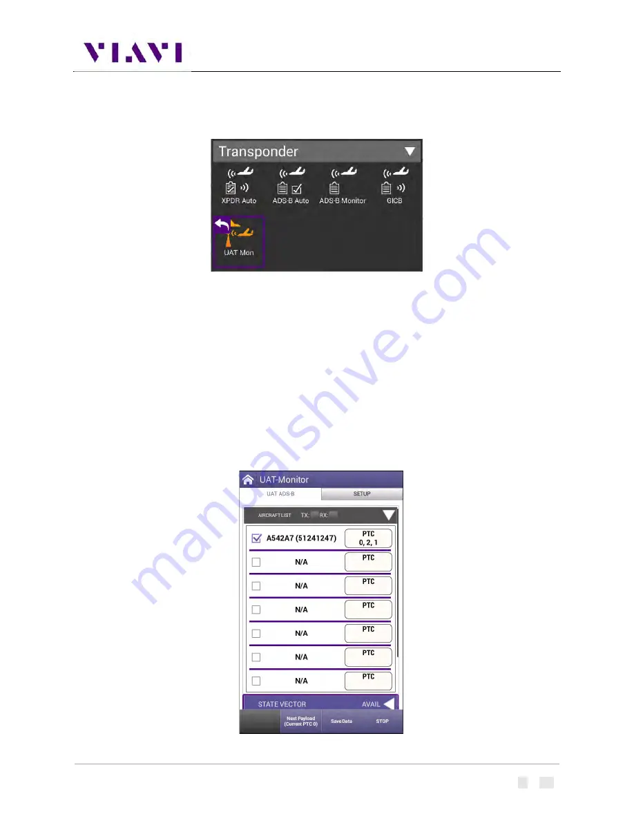
4.5.  UAT Monitoring 


4.5.1. 

Unique Setup 

Refer to Chapter 3 for common setup items.  For the UAT Monitor application, there are no unique 

settings in the SETUP tab. 


4.5.2. 

Run UAT Monitoring 

Press the RUN button to start received and decoding UAT Out information.  Each unique payload will be 
displayed on separate lines under the Aircraft List tab. 


Содержание AVX-10K

Страница 1: ...AVX 10K Flight Line Test Set Operations Manual ...

Страница 2: ...AVX 10K Flight Line Test Set Operation Manual PUBLISHED BY VIAVI Solutions Inc Original Issue AUG 2021 Re issued 001 MAR 2022 Re issued 002 AUG 2022 ...

Страница 3: ...3 Platform and System Features 11 1 4 Features and Capabilities 11 1 5 Device Software 11 1 6 First Time Use and Self Test 12 2 Setup Control and Operation 14 2 1 Control and Operation 14 2 2 Hardware 14 2 2 1 Controls and Buttons 16 2 2 2 I O Connectors 17 2 2 3 Hand Strap Rings 18 2 2 4 Status Indicators 18 2 2 5 Display Screen 19 2 3 Remote Operation 19 2 3 1 Mobile Tech Application 20 2 3 2 VN...

Страница 4: ...Server 40 2 10 5 Updating Test Set Software 43 2 10 6 Updating Software Options on AVX 10K 45 3 Test Application Common Settings Steps 47 3 1 Antenna Setups 47 3 1 1 Direct with Coupler 47 3 1 2 Over the Air 47 3 1 3 Direct to UUT 49 3 2 Common Setup Parameters 49 3 2 1 RF Port 50 3 2 2 Antenna Settings 51 3 2 3 Cable Settings 52 3 2 4 Coupler Settings 53 3 2 5 UUT Address 53 3 2 6 Position Settin...

Страница 5: ... Target Generation 82 5 1 TCAS 82 5 1 1 Unique Setup 82 5 1 2 Run TCAS Scenario 83 5 2 Target Gen 88 5 2 1 Unique Setup 88 5 2 2 Run Target Gen 89 5 3 UAT GEN 90 5 3 1 Unique Setup 90 5 3 2 Run UAT Gen 93 6 Navigation 95 6 1 Integrated Landing System ILS Operation 95 6 1 1 Setup 95 6 1 2 Run ILS Application 97 6 2 VHF Omnidirectional Ranging VOR Operation 101 6 2 1 Setup 101 6 2 2 Run VOR Applicat...

Страница 6: ...haracteristics 110 9 1 4 Equipment Needed for VSWR Test 111 9 2 Distance To Fault 115 9 2 1 DTF Test Function 115 9 2 2 Scope of DFT Test 116 9 2 3 Equipment Needed for DTF Test 116 10 System and Utility Functions 119 10 1 Introduction 119 10 2 System Functions 119 11 Battery Replacement 121 Appendix A AVX 10K Result Test Limits 126 Appendix B Caveats and Statements 131 Caveats and Statements 131 ...

Страница 7: ...7 Figure 8 Charge Status LED 19 Figure 9 Remote Operation Settings 22 Figure 10 IP Address Network ID 23 Figure 11 Home Screen Examples 26 Figure 12 Application Screen Examples 27 Figure 13 UI Header Info and Indicators 28 Figure 14 UI Shortcuts Panel 32 Figure 15 System Settings 33 Figure 16 StrataSync Update 43 Figure 17 Antenna Settings 51 Figure 18 VSWR Calibration Setup Diagram 111 Figure 19 ...

Страница 8: ...d this manual carefully before setting up or operating the instrument Product Nomenclature The following terms may be used in this Operations Manual to refer to the AVX 10K Flight Line Test Set AVX 10K AVX 10K test set Device Instrument Test Set Intended User This Operations Manual is intended for personnel who are familiar with avionic systems associated equipment and corresponding terminology Th...

Страница 9: ...d maintenance and troubleshooting procedures Product Brochure provides ordering information for parts and accessories Configuration Selection Guide provides information on configuration details Data Sheet provides technical specifications StrataSync User Guide provides operational information on the StrataSync Application Contact Information Contact VIAVI Customer Service for technical support or ...

Страница 10: ...test tool application is also provided that allows VSWR and Distance to Fault testing for cable and antenna troubleshooting Figure 1 AVX 10K Flight Line Operations Test Set The AVX 10K is supported with two free applications VIAVI s Mobile Tech application available from IOS App or Google Play Store provides remote control via your IOS or Android device as well as technical documentation and train...

Страница 11: ...AVX 10K Operation Rev 002 2022 08 25 22135254 VIAVI Page 9 of 139 Figure 2 Mobile Tech Application Figure 3 StrataSync Dashboard ...

Страница 12: ...em functionality such as network connectivity system updates and power management The AVX Application Module manages the device s RF test and measurement functions Testing with the AVX 10K can be performed in one of three methods Direct with Coupler Over the air using an antenna that can be mounted on the AVX 10K chassis Directly connected to the UUT Direct with Coupler Over the air Direct to UUT ...

Страница 13: ...WiFi and GPS receivers Smart Access Anywhere allowing VIAVI tech support to troubleshoot set up and test issues remotely Sleep Mode battery power saving mode 1 4 Features and Capabilities The AVX 10K supports testing of the following avionics functions 1 5 Device Software AVX 10K ships from the factory with the current version of Software SW and Firmware FW installed on the Device Routine maintena...

Страница 14: ...elieve there are issues with the test set Please run this procedure before returning the unit to the factory Turn the Test Set ON 1 Press and release the Power Button This is the green button at the bottom front of the test set An initializing indicator screen is displayed during the boot up process Wait while the device completes the boot up process Battery LED indicator is illuminated and the UI...

Страница 15: ...he prompts as directed A cable will be needed for External Loopback test This cable is supplied with each AVX 10K d When Self Test has completed running all tests verify that all portions of the test have passed If any portion of Self Test fails please contact VIAVI Customer Service Turn the Test Set OFF 1 Press and hold the Power button 1 second release the Power Button when the Front Panel displ...

Страница 16: ... Test Set can be operated locally using the touchscreen keypad or remotely using any mobile device with VIAVI s Mobile Tech application which is available at any online application store Optionally remote control of the AVX 10Kcan be accomplished via a VNC viewing application such as Tight VNC from a laptop or PC 2 2 Hardware Figure 5 Front View ...

Страница 17: ...AVX 10K Operation Rev 002 2022 08 25 22135254 VIAVI Page 15 of 139 Figure 6 Side View ...

Страница 18: ...conds When needed a hard reset is accomplished by pressing and holding the Power button for 10 seconds Back Button 6 The Back Button is used to exit a menu or to go back to the previous menu or screen If a data field is selected for editing selecting the Back Button exits the data field canceling an un confirmed change Home Button 7 Pressing the Home Button returns to the device s main home screen...

Страница 19: ... 2 2 I O Connectors The AVX 10K is equipped with three TNC type connectors on the AVX Application Module These connectors support test and measurement functions Figure 7 I O Connectors Caution Do not overload input connectors Refer to the product data sheet for maximum input ratings SWR Connector The Standing Wave Ratio SWR connector is used when performing VSWR and Distance to Fault DTF troublesh...

Страница 20: ...eive Indicator LED blinks green when the AVX 10K is receiving input from the device under test Error This LED is solid red indicates error and alarm conditions The type of error varies depending on the application Errors are displayed in the Utility Tray Batt multi color LED that indicates the battery status o Solid green indicates that either the battery charge is higher than 30 or that an extern...

Страница 21: ...d red indicates that the charging was suspended due to overheating The unit can continue to run no user intervention necessary 2 2 5 Display Screen The display screen is a Liquid Crystal Display LCD The LCD is a capacitive touchscreen that operates similar to a smart phone or tablet where you press to open select activate press and hold press and drag swipe sideways and pinch to zoom 2 3 Remote Op...

Страница 22: ... videos as well as file access so that you can view test reports from the connected device To connect wirelessly once the application is installed and you are able login the Mobile Tech application will search for nearby connectable devices Locate the ID of the AVX 10K that you want to connect to and press the CONNECT button Once connected press the Remote Display button and you will be able to vi...

Страница 23: ...ur tablet or phone s WiFi to the AVX 10K Go to your device settings enable WiFi and look for an SSID that starts with VIAVI ONX and connect Then in the Mobile Tech application type in the IP for the AVX 10K at the top of the screen where it says Enter an IP for Manual Connection and press the CONNECT button The default address for the AVX 10K device is 10 0 0 1 The Mobile Tech application should b...

Страница 24: ...A VNC viewing application must be installed on the computer AVX 10K test set and computer both devices must be connected to the same network Configure the AVX 10K Remote Operation via Systems Settings using your own VNC password This will be the password that the user of the VNC viewer software will need in order to gain access Figure 9 Remote Operation Settings ...

Страница 25: ...ddress field and select the OK Button to continue A password entry box appears 5 Enter the VNC password found on the Remote Operation menu and press the OK Button to submit The AVX 10K test set user interface appears in the VNC viewer 2 3 3 Smart Access Anywhere Application VIAVI s Smart Access Anywhere SAA application allows a remote user to be able to connect with the test set This could be a le...

Страница 26: ... to the server the application will generate a 10 digit hexadecimal code that will need to be shared with the person trying to connect with the test set Once the need for remote connectivity is complete click Disconnect in the lower right corner or reboot the test set to terminate the connected session To connect to the test set from the Smart Access Anywhere application enter the supplied 10 digi...

Страница 27: ...2 08 25 22135254 VIAVI Page 25 of 139 Once connected click the Remote Screen Page button and the application will allow you to control the test set Once you have completed the session click on the Session button and then Disconnect ...

Страница 28: ...ted Home Screen vs Application Screen 2 4 2 Home Screen Layout The Home Screen contains collapsible menus or ribbons that expand to provide access to system and test functions The functions that are available from the Home Screen varies according to the software and hardware options that are enabled on the device The Header Bar displays system indicators and the Utility Tray Icon which is used to ...

Страница 29: ...ain the Header Bar a main Display Area and a row of Function Soft Keys Function Soft Keys are selected using the touchscreen or the device s Function Hard Keys The content of application screens varies according to the application but layout is consistent from one application to another Figure 12 Application Screen Examples ...

Страница 30: ...e top indicators will look like this When connected to WIFI the top indicators will look like this Template Name If a template is being used this area will reflect the name of the selected template See Template Management in System settings for more information Figure 13 UI Header Info and Indicators Battery Status Indicator The Battery Status Indicator displays the charge level of the device s in...

Страница 31: ... The Network Connection Indicator is displayed when the device is connected to an active LAN via one of the device s Ethernet connectors WiFi Indicator The WiFi Indicator is displayed when the device is connected to a network via WiFi Wireless Indicator The Wireless Indicator is displayed when Wireless mode is enabled on the device System Error Indicator See Notifications for information about the...

Страница 32: ...ication Function Running Selecting the Back Arrow will disable or stop the application 2 6 UI Navigation UI screens are navigated using the following controls and techniques Expandable trays are opened and closed by selecting the directional arrow on the right side of the title bar Navigation arrows are used to move up down left right on the screen from a remote keyboard or from the device s front...

Страница 33: ... screen 3 Use the keypad to enter the data To switch from letters to numbers use the button in the lower left 123 or ABC On the alphabetic keypad the second key the up arrow is the shift key On the numeric keypad the second key 1 2 switches between multiple numeric screens The left pointing arrow with the x in it is the backspace key 4 Select the enter return key the fourth system key on the scree...

Страница 34: ...tcuts for up to four frequently used applications To create a shortcut Touch and hold the function icon drag and drop the icon to the Shortcut panel located at the bottom of the screen To remove or overwrite a shortcut To remove touch and hold the application icon in the shortcut panel drag and drop away from the shortcut panel or move an application icon to the Shortcut panel placing it over one ...

Страница 35: ... You can enter a password to be used for VNC viewer connectivity Wireless can be toggled on or off which can also be done from the system tray This screen will show the name of your device which is used to connect in the Mobile Tech app All paired devices are shown here as well as their connectivity state International Settings Country Language Keyboard type Measurement System Temperature Units an...

Страница 36: ...at whenever files are sent to your StrataSync account they are removed from the AVX 10K file folder You can also trigger a manual file purge from here to remove all reports Save Location This setting allows you to select where you want report files to be saved They can be saved locally to the AVX 10K file folders or to a connected USB drive or to both where applicable Restore Factory Defaults Rese...

Страница 37: ...Connection You must have an Ethernet LAN cable to establish an Ethernet connection to your instrument 1 Using an Ethernet cable connect the instrument to the LAN Connect one end of the Ethernet cable to the AVX 10K Ethernet connector located on the side panel and connect the other end of the Ethernet cable to the LAN 2 Verify that network connectivity is enabled 3 Go to the System menu then press ...

Страница 38: ...s IPv4 Gateway Enter the address for the gateway that is used to route packets that are not on the same subnet IPv4 DNS Server Enter the address of the DNS server Shared Share the IP from another interface for the multi interface mode If you specified IPv6 as your network mode specify the following settings IPv6 Address Mode DHCPv6 DHCPv6 Request Type Address Specify the address Prefix Specify the...

Страница 39: ...y the Tray menu and then press Network to establish the connection The instrument establishes an Ethernet connection to the LAN 2 10 2 Establishing a WiFi Connection The WiFi option allows you to establish a WiFi connection to a wireless network to 1 Synchronize your instrument to the StrataSync server 2 Export reports screenshots using FTP or 3 Update the firmware on your instrument Adding a WiFi...

Страница 40: ... Add WiFi Network menu appears 5 Specify the following settings SSID The SSID Service Set Identifier of the WiFi network Password The password required to authenticate to the network A password is not required if Key Management is set to None Key Management Open WEP or WPA WPA2 Personal Network Mode IPv4 IPv6 or IPv4 IPv6 Dual Stack Depending on the Network Mode you have one or more additional set...

Страница 41: ... been saved on your instrument but the network is out of range and therefore a connection cannot be established Incompatible A connection cannot be established to a network Connected The instrument has already established a connection to the network The instrument automatically connects to the network determined to provide the best available access point based on signal strength and or encryption ...

Страница 42: ... select Wireless The Wireless Settings menu appears 2 Press the box next to Enabled A checkmark appears 3 Press Scan for devices The instrument scans for Wireless devices then lists the devices on the menu 4 Select the device to connect If the instrument successfully authenticates to the device a message appears indicating that pairing was successful If the instrument does not successfully authent...

Страница 43: ...rataSync server StrataSync synchronization should be performed often as part of the instrument s operator level maintenance procedures to assure the latest firmware is installed To establish a StrataSync account refer to the Quick Start Guide for additional information and visit https www viavisolutions com en us products stratasync and click the REQUEST AN ACCOUNT link Preliminary Step Obtain or ...

Страница 44: ...nician and ID Software update milestones includes status and warnings if applicable If the configuration information contained on the server is newer than the information on the unit the server will be considered to be the most up to date The server will then send any files to the unit being synchronized that it determines are newer than those on the unit The device will then send any Reports Conf...

Страница 45: ... next to the version of the software to install Figure 16 StrataSync Update 2 Locate the test set or test sets that you would like to update and click the box in the left most column and YES on the next screen to proceed 3 Then from the AVX 10 test set that has been targeted for update select the START button from the StrataSync page Follow the prompts to finalize software update The unit will shu...

Страница 46: ... 6 Safely Eject and remove the USB Drive from your PC 7 Ensure the AVX 10K is connected to a power source 8 Insert the USB Drive into either of the two USB slots on the right hand access panel of the AVX 10K 9 Navigate to System Settings from the Menus a Select USB Software Update b The AVX 10 will automatically prompt you for the file on the root directory of your USB Drive c Accept the pop up fr...

Страница 47: ... the screen 2 All available software options will be displayed along with the available quantity for distribution 3 Double click on the option that you wish to deploy and select the AVX 10K that you wish to enable with this software option Ensure that the serial number of the AVX 10K is the correct device Click the checkbox to the left of the selected AVX 10K and choose Deploy from the Actions pul...

Страница 48: ...d receive a response indicating that the software option has been deployed Go to the StrataSync application on the AVX 10K that the software option has been deployed to and press the Start key in the lower right corner This will enable this AVX 10K to utilize this software option ...

Страница 49: ...be entered in the Setup tab 3 1 2 Over the Air The AVX 10K can also be used to test the onboard equipment using the over the air test setup When using this setup the antenna gain the height of the antenna and the distance from the antenna must be considered These values can also be entered in the Setup tab The antenna gain values can be found on the label of the antenna Caution Testing over the ai...

Страница 50: ...ting The AC10K ANT ILS antenna has a rubber base and can be extended The AC10K ANT MB antenna is short non extendable and rubber encased shown below on the right The intended usage for these antennas is described here Antenna Usage AC10K ANT ILS Non extended Usage Glide Slope testing Marker Beacon ELT 406 MHz Testing Extended Usage Localizer and ELT 121 5 243 MHz Testing AC10K ANT MB Specific Mark...

Страница 51: ...re are settings that are duplicated across many applications within the AVX 10K This section will detail those common settings of applicable test applications from the SETUP tab These include RF Port Antenna Direct Connect Direct Connect with Coupler Antenna Settings Range Height Gain 1 03 GHz 1 09 GHz Cable Settings Cable Length Cable Loss Coupler Settings UUT Address Position Settings Entry Meth...

Страница 52: ...ion specific settings will be discussed in the associated application sections below 3 2 1 RF Port There are three methods for any typical test setup Direct Connect with Coupler RF I O Antenna over the air and Direct Connect The RF Port setting allows you to select the test method ...

Страница 53: ...e active Set Top and Bottom Antenna Range and Height in accordance with the figure below Values can be selected by scrolling the vertical bar or using the plus and minus keys Note Top and Bottom settings are both available only when Diversity Test an application specific setting is ON Otherwise only Bottom Antenna settings will be available Figure 17 Antenna Settings ...

Страница 54: ...on the back of the RF flat panel antenna 3 2 3 Cable Settings The Cable Settings will be enabled when Direct Connect or Direct Connect with Coupler are selected as the RF Port setting Setting the Cable Length will drive an estimated cable loss If exact cable loss is known entering the value will override the provided estimate ...

Страница 55: ...ted tests the Unit Under Test UUT Address can be set to Auto or Manual If set to Manual you may enter the 6 character Hexadecimal address of the device being tested When set to Auto the test will interrogate the UUT and use the address in the reply as the UUT Address Note for the UUT to respond to a MODE S ALL CALL the aircraft must be in the airborne condition Manual Mode is used to target a spec...

Страница 56: ...ition used for ADS B and TCAS related testing You can select USER ENTRY or VIA GPS RX The GPS Receiver will allow you to use your local position If needed you can obtain your position using the GPS RX functionality of the AVX 10K GPS Position Format can be set to be displayed in Degrees Degrees Minutes or Degrees Minutes Seconds ...

Страница 57: ... as DF17 The DF18 option is used for beacons placed on obstacles around airports or in vehicles that are travelling around aircraft Position Decode Choose Global most common decodes two consecutive squitters to determine position or Local uses one squitter and entered GPS LAT LON position to determine position Verify Unit Setup Configuration when set to YES this will cause a pop up screen to appea...

Страница 58: ...ata button Pressing this button will bring up a list of Previously Saved Tests You can select any of these tests and then press the LOAD key and the main screen of the associated instrument will populate the fields and display the data in the state that it was displayed when the SAVE was performed This is an optional way to view report data ...

Страница 59: ...AVX 10K Operation Rev 002 2022 08 25 22135254 VIAVI Page 57 of 139 Note Overall Test Status and Ribbon Title may show NOT RUN but all of the fields below will be populated ...

Страница 60: ...n press SAVE to access the Save Test screen The Test Name can be overwritten or used as provided and saved locally by selecting the Save button The Job ID field is an open comments field that can be used for report filtering and within the StrataSync application Work Order ID is not used for this application Reports can then be saved onto a USB drive or sync d with the StrataSync application ...

Страница 61: ... Page 59 of 139 3 3 2 File Management The AVX 10K file browser is used to open rename copy or delete saved test result files screen shots or other files stored on the device Open the File Browser Expand the System ribbon and select the File Browser icon ...

Страница 62: ...AVX 10K Operation Rev 002 2022 08 25 22135254 VIAVI Page 60 of 139 Use the up and down arrow keys to navigate folders or files ...

Страница 63: ...e 61 of 139 Opening a File or Folder You can open a folder using any of the following Check the box next to the folder and select Open at the bottom of the page Tap anywhere on the folder field you wish to open Using the up down arrow keys and the OK button ...

Страница 64: ...AVX 10K Operation Rev 002 2022 08 25 22135254 VIAVI Page 62 of 139 Once opened a list of test results are shown in TXT HTML and json formats ...

Страница 65: ...ed by users for report generation in supporting programs HTML format is readable on the device as shown below and as a downloaded file test report Note in the tray there is a View Reports icon where all HTML reports can also easily be viewed on the device This is the quickest and most concise way of viewing reports ...

Страница 66: ...er or Copy to Internal if you are using the USB File Browser 4 The file is copied and the File Browser menu appears Upload Files 1 Open the File Browser 2 Select a file or folder 3 Press the File Options system key and then select Upload FTP HTTP The Upload settings appear 4 Specify the Upload URL Username and Password 5 Select and press the Apply button to start the upload When the upload finishe...

Страница 67: ...ity on off Set to On to test both top and bottom antennas for a diversity system and Diversity Isolation Test Altitude Settings This item gets enabled when ALTITUDE CHECK is selected as the Test Configuration Here you can enter various Altitudes that will get stepped through when running the ALTITUDE CHECK test Power Units Allows for measured power to be displayed in Watts or dBm ...

Страница 68: ...Test Configuration Box is shaded identifying it as an active field By selecting this it will show all available test configurations Select desired test from the provided list Note Transponder class and option identification are found on the transponder s TSO label Configuration Description FAR Part 43 MODE S Runs only the tests associated with FAR Part 43 Appendix F as required by 91 413 test requ...

Страница 69: ... Class A transponders MODE S CL B Tests Mode S Class B transponders MODE S CL B OPT POW Tests Mode S Class B transponders equipped with Class A power option MODE S CL B OPT FREQ Tests Mode S Class B transponders equipped with Class A frequency tolerance option ATCRBS CL A Tests ATCRBS Class A transponders ATCRBS CL B Tests ATCRBS Class B transponders At the bottom of the page you will see the Test...

Страница 70: ... ribbon to see the resultant failure If any of the individual test ribbons are expanded and the Run button is selected you will be asked if you want to loop on that specific expanded ribbon test which will also include all expanded ribbons or run a complete test The expanded test options are listed below the RUN button ...

Страница 71: ...figured fields the AVX 10K only displays the decoded data and cannot determine PASS FAIL criteria for these fields Note In the test results the nomenclature ITM refers to Intermode Intermode is when a Mode A or C Interrogation is tested along with a Mode S Interrogation See Appendix A for more details on XPDR Auto Test Results 4 1 2 1 Run Encoder Test To capture altitude results with a faster inte...

Страница 72: ... Description NOT RUN RUN button has not yet been pressed NO REPLY UUT has not yet provided the information UUT may be in ground state and will not reply to Mode S ALL CALL Transponders only replies to discrete interrogations when in ground state NOT CAPABLE Test will not be run as the UUT is not able to provide this information PASS Test concluded PASSED FAIL Test concluded FAILED If you choose to...

Страница 73: ...AVX 10K Operation Rev 002 2022 08 25 22135254 VIAVI Page 71 of 139 4 2 ADS B Auto 4 2 1 Unique Setup Refer to Chapter 3 for common setup items ...

Страница 74: ... DF Setting Choose DF17 typical for Mode S transponders or DF18 1090MHz emitters Most often this should be left as DF17 The DF18 option is used for beacons placed on obstacles around airports or in vehicles that are travelling around aircraft Advanced Position Decode Choose Global most common decodes two consecutive squitters to determine position or Local uses one squitter and entered GPS LAT LON...

Страница 75: ...ration Rev 002 2022 08 25 22135254 VIAVI Page 73 of 139 Once the Airborne tests have completed move to the Surface screen set the aircraft under test in the surface mode weight on wheels and select the Run button ...

Страница 76: ...9 Once the testing completes successfully the screens will look similar to this Note If the HEADING field is displayed in yellow typical this is because the aircraft is stationary If you choose to save your test results please refer to Chapter 3 for managing reports ...

Страница 77: ...g Choose DF17 typical for Mode S transponders or DF18 1090MHz emitter Most often this should be left as DF17 The DF18 option is used for beacons placed on obstacles around airports or in vehicles that are travelling around aircraft Advance Position Decode Choose Global most common decodes two consecutive squitters to determine position or Local uses one squitter and entered GPS position to determi...

Страница 78: ... was received NOT RUN test has not yet been run BAD SETUP This can happen for a number of reasons 1 An ADS B Version Number earlier than DO 260B is being broadcast 2 The RF input was overloaded at the beginning of the test usually indicates that antenna range height and or cable loss values are incorrect If you choose to save your results press the Save Data softkey and please refer to Chapter 3 f...

Страница 79: ...fer to Chapter 3 for common setup items Setting Definition Advance GICB Downlink Format Choose DF20 or DF21 Typically left as DF20 This option is available for change due to the transponder specification Advance Position Decode Choose Global most common decodes two consecutive squitters to determine position or Local uses one squitter and entered GPS position to determine position ...

Страница 80: ...nitoring The default mode Simple Mode will query for common GICB register values Toggle the mode by pressing the Simple Mode key and the test set will query for all GICB registers Adv Mode If you choose to save your results please refer to Chapter 3 for managing and viewing reports ...

Страница 81: ...up Refer to Chapter 3 for common setup items For the UAT Monitor application there are no unique settings in the SETUP tab 4 5 2 Run UAT Monitoring Press the RUN button to start received and decoding UAT Out information Each unique payload will be displayed on separate lines under the Aircraft List tab ...

Страница 82: ... 08 25 22135254 VIAVI Page 80 of 139 Press the Next Payload softkey at the bottom of the screen to display details for each payload Any decoded information received from the UUT will be displayed in the associated tabs as shown here ...

Страница 83: ...AVX 10K Operation Rev 002 2022 08 25 22135254 VIAVI Page 81 of 139 Press the Save Data button to capture and store the received information ...

Страница 84: ...p parameters are found on the SETUP tab for the TCAS application Setting Description Test Set Address Enter a 6 digit Hexadecimal address other than the address of the unit under test Squitters Toggles between ON and OFF Altitude Reporting Toggles between ON and OFF Display Altitude Toggles between RELATIVE and ABSOLUTE ERP Units Allows for measured power to be displayed in Watts or dBm ...

Страница 85: ...nd ON This can be used to bypass the Aircraft Baro Test Altitude entry below which will be disabled when this is set to ON In that case the altitude of the unit under test UUT is obtained from the squitter information NOTE This information will be available when testing over the air When using a TCAS Coupler the TCAS may not be able to get information from the Transponder Obviously this is not the...

Страница 86: ...AVX 10K Operation Rev 002 2022 08 25 22135254 VIAVI Page 84 of 139 ...

Страница 87: ...e background shown here will be updating and will turn to a green background You can click on the tabs or swipe right to view the additional data When the intruder type is toggled to ATCRBS as shown below the SURVEILLANCE and BROADCAST tabs are replaced by the WHISPER SHOUT tab where you can increase or decrease attenuation by pressing the associated buttons ...

Страница 88: ...AVX 10K Operation Rev 002 2022 08 25 22135254 VIAVI Page 86 of 139 ...

Страница 89: ...002 2022 08 25 22135254 VIAVI Page 87 of 139 If you created a new profile you may choose to save for later use by pressing the Save Profile button selecting one of the custom fields and then pressing the Save Scenario button ...

Страница 90: ...elect between ADS B ADS R and TIS B ADS B Type Toggles between AIRBORNE and SURFACE and only available when Target Type is set to ADS B Latitude Set to Latitude of UUT Longitude Set to Longitude of UUT Heading Enter a value between 0 and 359 degrees Altitude Enter a value between 1000 and 126700 feet Target Settings repeated for five targets Description Flight ID Enter up to eight characters Aircr...

Страница 91: ... Altitude Rate Select between CLIMB LEVEL DESCEND 5 2 2 Run Target Gen This application will allow you to set up to five static intruders for testing of ADS B In Receivers Any of the fields with a blue background are editable The data in the Target settings are referenced from the Aircraft Under Test Each Target can be disabled or enabled by toggling the button ...

Страница 92: ...f the custom fields and then pressing the Save Configuration button 5 3 UAT GEN 5 3 1 Unique Setup Refer to Chapter 3 for common setup items For the UAT Traffic Generation application there are no unique settings in the SETUP tab however the main screen of the UAT GEN application has a number of configurable parameters These configurable fields have a blue background ...

Страница 93: ... 6 hexadecimal characters Bearing Enter a value between 0 and 359 degrees to define the bearing in relation to the UUT Heading Enter a value between 0 and 359 degrees Altitude Enter a value between 3500 and 3500 feet to define the vertical distance from the UUT Altitude Rate Select between CLIMB LEVEL DESCEND Range Enter a value between 0 and 40 nautical miles to define the distance from UUT This ...

Страница 94: ...B Weather Description Report Select between METAR and TAF the predefined settings will be displayed in the Weather Data section at the bottom of the screen Day Time Allows setting Day to a value between 0 and 31 Hour to a value between 0 and 23 and Minute to a value of 0 to 59 Station Select between KMCI KAUS KFFC KBNA and PANC Slot ID Select between a value of 0 to 31 ...

Страница 95: ...ming parameters Should this screen popup it is a notification that the unit is likely past the calibration schedule If that is not the case press the OK button to continue with testing On the main page of the UAT Gen application any of the fields with a blue background are editable The data in the Target settings are referenced from the Aircraft Under Test Each Target can be disabled or enabled by...

Страница 96: ...ev 002 2022 08 25 22135254 VIAVI Page 94 of 139 FIS B information can also be sent using this application by selecting the FIS B tab setting up the configurable parameters as defined above and then pressing the RUN button ...

Страница 97: ... antenna testing or direct connection to the LRU RF Power Units Can be set to dBm or V Volts in 50 ohms Frequency Input Type PRESET CHANNEL OR VAR PRESET provides a set of three fixed frequencies CHANNEL allows the selection of any on channel frequency VAR allows selection of frequency in 1kHz steps may not be available in every instrument setup ILS Units This parameter determines the Localizer an...

Страница 98: ...screen to be adjusted in step values Numeric Entry allows for any value in the defined range to be entered Localizer Frequency Step Allows Localizer Frequency step value to be selected between 0 001 MHz 0 010 MHz 0 100 MHz 1 000 MHz Glide Slope Frequency Step Allows Glide Slope Frequency step value to be selected between 0 001 MHz 0 010 MHz 0 100 MHz 1 000 MHz Marker Variable Frequency Step Allows...

Страница 99: ... by the ILS Application include Setting Definition ILS Tri Mode Localizer Glideslope and Marker Beacon are enabled ILS Dual Mode Only Localizer and Glideslope are enabled ILS Localizer Only Localizer is enabled ILS Glideslope Only Glideslope is enabled ILS Marker Beacon Only Marker Beacon is enabled Off Nothing is enabled Below are examples of the screens in each mode TRI MODE All Instruments On D...

Страница 100: ... popup might appear that helps to drive you to one of these available modes To review the configurable fields in the main body of the ILS Application let s look at the screen with all functionalities enabled ILS TRI MODE Each of the subsequent screens will look similar to this screen or have a subset of the fields displayed Note Tri Mod where all instruments are enabled is only available when test...

Страница 101: ... when the LOC DDM field is a non zero position value or when the M MOD field is NOT set to CAL and the LOC DDM field is a non zero position value If set to µA FIXED provides CENTER LEFT and RIGHT deviation values at 0 90 150 and 194 µA VARIABLE provides CENTER LEFT and RIGHT deviation values from 0 to 388 µA in 1 µA steps UNCAL is displayed when set to VAR and the LOC DDM Field is in a Non Zero po...

Страница 102: ... DOWN 0 0 CENTER 0 091 78 UP 0 175 150 UP 0 400 343 UP Once you reach a value at the extreme the Arrow key will change from blue to gray in color Also the Glide Slope can be modified by selecting the horizontal bar on the display and moving it to the desired location If DEV STEP is set to FIXED the bar will snap to the nearest value M MOD Opens a window with slider controls to allow adjustment of ...

Страница 103: ...utton This allows all of the values on the main page to be saved for later recall as needed Center Deviation button This sets the LOC and G S offsets to zero 6 2 VHF Omnidirectional Ranging VOR Operation 6 2 1 Setup The settings for the VOR application are described in the table below ...

Страница 104: ...on 0 0 to 22 0 dB of an External Attenuator on the RF I O Connector This is used for extending the power monitor rating and range If the External Attenuator is selected the value is displayed on all Mode Screens in the EXT ATTN Field under the RF LVL Field Morse Code Up to four characters that are used to transmit Morse Code for ILS Localizer The main screen of the VOR application also contains co...

Страница 105: ...ick in the center of the control to pull up a popup window for selection When set to CHANNEL the UP DOWN Arrow keys will increment or decrement values based on the selected CHAN STEP SIZE CHAN STEP SIZE is selected by clicking in the center of the control Selections include 05 15 MHz and 5 1 MHz When set to VAR the UP DOWN Arrow keys will increment or decrement values based on FREQ STEP SIZE FREQ ...

Страница 106: ...components The Master Modulation Depth is the sum of the Depths of Modulation SDM of the individual tone components TONE DELETE This field allows the 30 Hz Reference 30 Hz Variable or both to be deleted Press anywhere on this control for the popup selection window 30 Hz MOD This field controls the value of the 30 Hz Variable Phase modulation depth Use the UP Down Arrow keys to adjust the value in ...

Страница 107: ...se code ident Squitter Sets squitter output to ON or OFF Maximum Range Enter a maximum range value from 0 to 450 nm UUT ERP Units Allows for measured power to be displayed in Watts or dBm The main screen of the DME application also contains configurable parameters These configurable fields have a blue background The available fields will be different based on the Frequency Entry Type detailed abov...

Страница 108: ...e toggles between X and Y Paired VOR Frequency and TX Frequency will change accordingly Range nm Enter a value between 0 and 450 nautical miles Range Rate kts Enter a value between 0 and 6500 knots Range Direction Toggles between IN and OUT Reply Enter a value between 0 and 100 percent reply Echo Toggles between ON and OFF Identification Toggles between OFF TONE and IDENT RF Level dBm Enter a valu...

Страница 109: ...AVX 10K Operation Rev 002 2022 08 25 22135254 VIAVI Page 107 of 139 ...

Страница 110: ...022 08 25 22135254 VIAVI Page 108 of 139 7 Radio Test COMMS 7 1 VHF COM Amplitude Modulation AM Reserved 7 2 VHF COM Frequency Modulation FM Reserved 7 3 COM High Frequency HF Single Side Band SSB Reserved 7 4 COM SelCal Reserved ...

Страница 111: ...AVX 10K Operation Rev 002 2022 08 25 22135254 VIAVI Page 109 of 139 8 ELT 8 1 ELT 121 5 Reserved 8 2 ELT 243 Reserved 8 3 ELT 406 Reserved ...

Страница 112: ...the ratio of the reflected signal to the transmitted signal A low return loss indicates less signal reflection and better signal strength A high return loss indicates more signal reflection and less signal strength indicating an issue along the transmission line When Return Loss is selected measurements are displayed in dB 9 1 2 Scope of VSWR Test This test is used to evaluate how well an antenna ...

Страница 113: ...procedures defined in this section Cable or antenna to be tested Calibration Kit short cable with short and load included with the AVX 10K Run VSWR Calibration 1 It is recommended that the VSWR calibration be performed prior to testing any antenna or cable 2 Connect the short TNC to TNC cable to the AVX 10K as shown Figure 18 VSWR Calibration Setup Diagram ...

Страница 114: ...e Home screen 5 Select the VSWR DTF application 6 Select the VSWR tab 7 Press the Calibrate soft key 8 Select External Standards Select OK button to confirm 9 Follow the instructions at the bottom of each screen to perform Open Short Load calibration The short is the smaller of the two terminators Press SAVE button to complete ...

Страница 115: ...AVX 10K Operation Rev 002 2022 08 25 22135254 VIAVI Page 113 of 139 10 When external calibration has been completed the calibration plot should resemble the following figure ...

Страница 116: ...ower on the AVX 10K 2 Select the Test Tools ribbon on the Home screen 3 Select the VSWR DTF application 4 Select the VSWR tab 5 Open the Instrument Settings menu 6 Set the Start Frequency to 900 MHz 7 Set the Stop Frequency to 1250 MHz 8 Open Instrument Settings set Measurement Mode to VSWR and press the OK button 9 Ensure the VSWR soft key is set to VSWR On ...

Страница 117: ... for 1030 MHz and 1090 MHz which indicates a good antenna A poor antenna would have high VSWR values in this band 9 2 Distance To Fault 9 2 1 DTF Test Function Distance to Fault DTF is an analysis that is used to identity signal path degradation in cables and transmission lines that may be a result of conditions such as poor connections damaged cables or faulty antennas ...

Страница 118: ...lowing performance issues The distance to fault of a coaxial cable 9 2 3 Equipment Needed for DTF Test The following equipment is required to perform the procedures defined in this section Cable to be tested TNC adapter if applicable to interface with the AVX 10K SWR port Perform DTF Test Figure 20 DTF Test Setup Diagram Configure the AVX 10K for DTF Test 1 Power on the AVX 10K 2 Select the Test T...

Страница 119: ... instrument settings menu 7 Set measurement mode to Return Loss 8 Open the instrument settings menu and set the stop distance to a distance longer than the cable under test 9 Close the instrument settings tab and ensure the DTF enable soft key displays DTF on 10 The AVX 10K will display the DTF trace ...

Страница 120: ...rker to the peak which reflects a fault indication to determine the distance to fault The markers can be moved manually or using the peak buttons at the bottom of the screen The middle button is peak find and the adjacent buttons are next peak left or right if additional peaks exist ...

Страница 121: ...ireless access The Test Set contains built in signal generators and modulators for XPDR frequencies System and utility functions also support file management user setup information and updating the device s software and firmware 10 2 System Functions System functions are accessed from the System Menu on the device s Home Screen System Settings are discussed in Section 2 12 Figure 21 System Main Sc...

Страница 122: ...rowser File Browser Similar to a file browser on a computer Additionally you can select files to be copied to an FTP server that you specify Once a file or group of files is selected press the File Options button and enter the FTP server URL and associated username and password and click Apply If a valid FTP connection is made the files will be transferred Job Manager Not used Diagnostics Allows a...

Страница 123: ...e Battery 1 Place the test set on a suitable work bench with the display facing down 2 Loosen but do not fully remove the six flat blade captive screws that secure the module to the base unit The screws are identified with the battery symbol There is no need to remove the eight phillips head screws as the back shell can stay mounted to the module ...

Страница 124: ...r seal If module sticks to the base unit insert a screwdriver where pry slots are provided and gently pry until module releases 3 Disconnect the module from the base unit while carefully avoiding damage to the PCB assembly If module sticks to the base unit insert a screwdriver where pry slots are provided and gently pry until module releases ...

Страница 125: ...2 2022 08 25 22135254 VIAVI Page 123 of 139 4 Loosen the screw that secures the battery cover and remove the cover to expose the battery 5 Push tab on battery cable connector clip to release and pull cable away from connector ...

Страница 126: ...AVX 10K Operation Rev 002 2022 08 25 22135254 VIAVI Page 124 of 139 6 Remove battery from the device Dispose of the old battery according to local regulations ...

Страница 127: ...he battery is properly inserted in the device 1 Insert the new battery in the battery compartment Caution When installing the new battery use care to ensure wires are inside the compartment Damage may occur if wires are pinched by the cover 2 Align and connect the module to the base unit Verify the module is flush on the base unit before proceeding 3 Screw in the six screws to secure the Module Co...

Страница 128: ...raph g S code Mode A code being reported in the Mode S reply FAR 43 Appendix F paragraph g A ALT Mode S altitude being reported in the Mode S reply FAR 43 Appendix F paragraph g BOT Frequency Frequency of the bottom port replies test criteria For class A transponders 1090 00 MHz 1 For class B transponders 1090 00 MHz 3 FAR 43 Appendix F paragraph a BOT ERP For class A transponders 51dBm For class ...

Страница 129: ...h Power and Frequency ribbon Mode A MTL 73 4 dBm FAR 43 Appendix F paragraph Mode A ERP For class A transponders 51dBm For class B transponders 48dBm Transponders must not exceed 57dBm FAR 43 Appendix F paragraph d Mode A frequency Frequency of the bottom port replies test criteria For class A transponders 1090 00 MHz 1 For class B transponders 1090 00 MHz 3 FAR 43 Appendix F paragraph a A C MTL D...

Страница 130: ...rmode Reply address for Mode A FAR 43 Appendix F paragraph g Mode C ITM reply ADDR Intermode Reply address for Mode C FAR 43 Appendix F paragraph g Mode S ALL CALL Capability Displays the capability of the transponder from the DF11 reply FAR 43 Appendix F paragraph h Mode S ALL CALL Address Displays the address in the ALL CALL reply FAR 43 Appendix F paragraph h Mode S ALL CALL Reply Status Indica...

Страница 131: ...n the DF11 squitter FAR 43 Appendix F paragraph h UF5 ribbon DF5 Was the reply to this interrogation a DF5 FAR 43 Appendix F paragraph g AC Displays the Mode 3 Code in the DF5 FAR 43 Appendix F paragraph g Mode C ALT Compare Compares the Mode 3 Code to the Mode 3 code contained in the DF5 reply FAR 43 Appendix F paragraph g AA Announced Address in the DF5 reply FAR 43 Appendix F paragraph g DF11 A...

Страница 132: ...dress in the DF20 reply FAR 43 Appendix F paragraph h UF21 ribbon DF Displays the DF reply to the UF21 FAR 43 Appendix F paragraph h Mode A ID Compare Compares the Mode 3 ID from the Mode 3 reply to the ID in the reply from the UF21 FAR 43 Appendix F paragraph h DF11 Address Compare Compares the address from the DF11 squitter to the address in the DF20 reply FAR 43 Appendix F paragraph h Note Thes...

Страница 133: ...er VIAVI Solutions and the VIAVI logo are trademarks of VIAVI Solutions Inc VIAVI All other trademarks and registered trademarks are the property of their respective owners Copyright Release Reproduction and distribution of this guide is authorized for US Government purposes only Patent Information Patented as described at https www viavisolutions com en us corporate legal patents Warranty Informa...

Страница 134: ...t includes third party software licensed under the terms of separate open source software licenses By using this software you agree to comply with the terms and conditions of the applicable open source software licenses Software originated by VIAVI is not subject to third party licenses Terms of the VIAVI Software License different from applicable third party licenses are offered by VIAVI alone Sa...

Страница 135: ...that the equipment or battery must not be disposed of in a land fill site or as municipal waste and should be disposed of according to your national regulations CE Compliant This Marking indicates the item meets the conformity requirements of the European Union UKCA Compliant This Marking indicates the item meets the conformity requirements of the Great Britain England Scotland and Wales A copy of...

Страница 136: ...gn Type Certification Certify construction design of an equipment and test per model to which the Giteki mark and ID number is granted The Certification does not limit the quantity of the equipment as long as the equipment is manufactured by the same design and the manufacturing method is applied as the certified model The Specified Radio Equipment connected to telecommunication network requires c...

Страница 137: ... device in a manner not specified in accompanying documentation may impair the safety protection built into the device This device is designed and tested to comply with the requirements of IEC EN 61010 1 3rd Edition Safety Requirements for Electrical Equipment for Measurement Control and Laboratory Use for Class I portable equipment and is for use in a pollution degree 2 environment Toxic Hazards ...

Страница 138: ...RNING Residual Current The supply filter contains capacitors that may remain charged after the instrument is disconnected from the power supply The residual energy is within the approved safety requirements however a slight shock may be felt if the plug pins are touched immediately after removal Caution Input Overload Do not overload input connectors Refer to product Safety and Compliance Specific...

Страница 139: ...esigned to provide reasonable protection against harmful interference when the equipment is operated in a commercial environment This product generates uses and can radiate radio frequency energy and if not installed and used in accordance with the instruction manual may cause harmful interference to radio communications Operation of this product in a residential area is likely to cause harmful in...

Страница 140: ...n 65 California Proposition 65 officially known as the Safe Drinking Water and Toxic Enforcement Act of 1986 was enacted in November 1986 with the aim of protecting individuals in the state of California and the state s drinking water and environment from excessive exposure to chemicals known to the state to cause cancer birth defects or other reproductive harm VIAVI s position statement on the us...

Страница 141: ...AVX 10K Operation Rev 002 2022 08 25 22135254 VIAVI Page 139 of 139 Appendix C Safety Data Sheets Safety Data Sheets Rechargeable Lithium Ion Batteries ...

Страница 142: ...ontact Chemtrec 1 800 424 9300 US and Canada 1 703 527 3887 International 2 Hazard s identification There are no hazards when measures for proper handling and storage are followed In case of damage to a battery cell there is danger of release of hazardous substances including a highly flammable gas mixture and dangerous levels of heat In case of fire there is danger of release of hazardous combust...

Страница 143: ...this without risk For a small fire use dry chemical CO2 water spray or regular foam For a large fire use water spray fog or regular foam Fire fighting personnel should use a self contained breathing apparatus Detailed information on fighting a lithium ion battery fire can be found in Guide 147 Lithium Ion Batteries of the US DOT Emergency Response Guide 6 Accidental release measures Under normal c...

Страница 144: ...drogen fluoride HF The electrolyte may form a small amount of hydrofluoric acid on contact with water 10 Stability and reactivity Lithium ion batteries are chemically stable Keep away from open flame hot surfaces and sources of ignition Do not puncture crush or incinerate cells If cells are punctured crushed or incinerated hazardous decomposition byproducts include carbon monoxide carbon dioxide f...

Страница 145: ...eparately from the product This is not required for other modes of transportation only air and is not required when the batteries are contained in the product or packed with the product in the same package The shipper must also be aware of other requirements that are defined in the international regulations such as the nature of the packaging materials the per package quantity limit the required l...

Страница 146: ...ithium ion batteries used in all VIAVI Solutions products meet the international requirements for shipping by ground or rail Consult national regulations for other requirements packaging documentation training per package quantity limit Consult your shipping company or freight forwarder ahead of time 15 Regulatory information All lithium ion batteries sold by VIAVI Solutions have been tested and f...

Страница 147: ... North America 1 844 GO VIAVI 1 844 468 4284 Latin America 52 55 5543 6644 EMEA 49 7121 862273 APAC 1 512 201 6534 All Other Regions viavisolutions com contacts 22135254 Rev 002 Part of CD 22141759 August 2022 English ...

Отзывы: