background image


v09/2020 


20


8. 

WARRANTY STATEMENT


VFTECH  warrants  that  at  the  time  of  shipment,  all  products  shall  be  free  from  defects  in  material  and 
workmanship  and  suitable  for  the  purpose  specified  in  the  product  literature.  The  unit/system  warranty 
commences immediately from the date of customer acceptance and runs for a period of 1 year 

(except for 

thrusters)

. Warranty for thrusters is 6 months from the date of purchase. Customer acceptance will always 

be deemed to have occurred within 72 hours from delivery. 

Note: 

Any customer acceptance testing (if applicable) must be performed at either VFTECH premises, or at 

one of their approved distributors, unless mutually agreed in writing prior to dispatch. 

The warranty service is conditioned by regular inspections every three months starting from the date of 
customer acceptance of the device. If the regular maintenance checks are not performed, the warranty is 
not applicable. 

Conditions: 

These include, but are not limited to, the following: 

1.  The  warranty  is  only  deemed  to  be  valid,  if  the  equipment  was  sold  through  VFTECH,  or  one  of  its 
approved distributors. 

2.  The  equipment  must  be  installed  and  commissioned  in  strict  accordance  with  approved  technical 
standards and specifications, and for the purpose that the system was designed for. 

3. The warranty is not transferable, except for as applies to Purchaser first, then to the  client. 

4. VFTECH must be notified immediately (in writing) of any suspected defect, and if advised by VFTECH, 
the equipment subject to the defect shall be returned by the customer to VFTECH, via a suitable mode of 
transportation and shall be freight paid. 

5.  The  warranty  does  not  apply  to  defects  that  have  been  caused  by  not  following  the  recommended 
installation  or  maintenance  procedures.  Neither  the  defects  resulting  from  normal  wear  &  tear,  incorrect 
operation, fire, water ingress, lightning damage, the fluctuations in vehicles supply voltages, nor from any 
other  circumstances  that  may  arise  after  delivery,  that  is  without  the  control  of  VFTECH.  (Note:  The 
warranty does not apply in the event where a defect has been caused by isolation incompatibilities.) 

6.  The  warranty  does  not  cover  the  transportation  of  personnel  and  per  diem  allowances  relating  to  any 
repair or replacement. 

7.  The  warranty  does  not  cover  any  direct,  indirect,  punitive,  special  consequential  damages,  or  any 
damages whatsoever arising out of or connected with misuse of this product. 

8.  Any  equipment  or  parts  returned  under  warranty  provisions  will  be  returned  to  the  customer  freight 
prepaid by VFTECH. 

9.  The  warranty  shall  become  invalid,  if  the  customer  attempts  to  repair  or  modify  the  equipment  without 
appropriate written authority being first received from VFTECH. 

10. VFTECH retains the sole right to accept or reject any warranty claim. 

11. Each product is carefully examined and checked before it is shipped. It should therefore be visually and 
operationally checked, as soon as it is received. If it is damaged in anyway, a claim should be filed with the 
courier and VFTECH notified of the damage. 

Note:  VFTECH  reserve  the  right  to  change  the  specifications  at  any  time  without  notice  and  without  any 
obligation to incorporate new features in instruments previously sold. 

 
Note:  If  the  instrument  is  not  covered  by  warranty,  or  if  it  is  determined  that  the  fault  is 
caused  by  misuse,  the  repair  will  be  billed  to  the  customer,  and  an  estimated  price 
submitted for customer approval before the commencement of repairs. 


Содержание GNOM BABY

Страница 1: ...Y Operator manual Vapenicka 24 971 01 Prievidza Slovakia Tel Fax 421 46 54264 56 https www vftech sk https www rov 2020 remotely operated vehicle VFTECH spol s r o Vapenicka 24 971 01 Prievidza Slovak...

Страница 2: ...hnical specifications 6 2 User s manual for operation with GNOM 7 3 Keys and Buttons at the control panel 12 4 Screen modes 15 5 Calibration 16 6 Maintenance operation 17 7 Safety requirements 19 8 Wa...

Страница 3: ...ayed on the monitor TV receiver or sent to the digital video recorder if supplied via standard AV cable There are two video output connectors at surface control module that allow to connect two displa...

Страница 4: ...v09 2020 4 1 DESCRIPTION 1 2 DESIGN Recommended configurations Hand reel Coaxial cable Underwater module Power supply control module Joystick Waterproof transport cases LCD monitor...

Страница 5: ...hts main hull The plastic float is fastened by the nut and the Screw propellers are installed at the end of the thruster ax the power supply converter electronic module and depth sensor are installed...

Страница 6: ...ressing one of the buttons on the joystick the operator can enter the menu to tune up some of the functions such as calibrating of the depth sensor 1 2 TECHNICAL SPECIFICATION 3 magnetically coupled t...

Страница 7: ...of the vehicle by adding additional weights on the plastic feet Note that the cable weight in water is approximately 2 g m 2 3 Plug the 3 pin connector to the reel and video cable to the monitor video...

Страница 8: ...he RCBO Checking the RCBO residual circuit breaker with overcurrent protection must be performed before any underwater operation at the new location If the requirements of paragraph 2 4 1 are met conn...

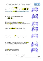
Страница 9: ...s the arrows Left Right Up Down power use the left joystick right joystick ANALOG HOME v09 2020 USER S MANUAL FOR OPERATION 30V ON UP position switch it on separately Brightness contrast on can be adj...

Страница 10: ...1 or Mode2 or Mode3 see below You can choose the menu language Russian English SELECT L 1 L 2 R 2 R 1 R 2 v09 2020 USER S MANUAL FOR OPERATION to change the intensity of the front 100 100 0 Press 100...

Страница 11: ...h water Special Functions Sleep mode Power Saving Mode In order to save the power and extend the battery life the wireless joystick has a power saving mode The joystick enters sleep mode power saving...

Страница 12: ...v09 2020 12 3 KEYS AND BUTTONS AT THE CONTROL PANEL...

Страница 13: ...v09 2020 13 3 KEYS AND BUTTONS AT THE CONTROL PANEL...

Страница 14: ...v09 2020 14 3 KEYS AND BUTTONS AT THE CONTROL PANEL...

Страница 15: ...v09 2020 15 4 SCREEN MODES...

Страница 16: ...calibrate the compass follow the Calibration procedure 1 Put the GNOM on flat surface away from metal objects with the dome pointing North 2 Press circle right key to start the calibration 3 Slowly tu...

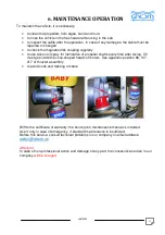
Страница 17: ...rication of propeller shafts every time after diving Oil must get inside the cone shaped heads of motors See appendix position 96 147 217 of thruster assembly to avoid nods and twisting of cable Withi...

Страница 18: ...cover VULCANIZING TAPE use for temporary repair of damaged cable damaged insulation FUSES use if the fuses installed in the power module are destroyed SEALING O RINGS use if the cable in the underwate...

Страница 19: ...on and off by main 230V switch which is placed over the power cord on the surface control unit 3 Do not use the system with the damaged cable 4 Do not touch the underwater vehicle and the cable if you...

Страница 20: ...arranty does not apply to defects that have been caused by not following the recommended installation or maintenance procedures Neither the defects resulting from normal wear tear incorrect operation...

Страница 21: ...v09 2020 21 9 EXAMPLES OF MODULE LINKING...

Страница 22: ...v09 2020 22 9 EXAMPLES OF MODULE LINKING...

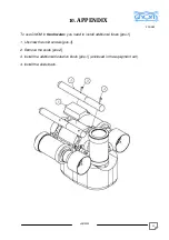
Страница 23: ...To use GNOM in fresh water you need to install additional floats pos 1 1 Unscrew the skid screws pos 3 2 Remove the skids pos 2 3 Install the additional floatation block pos 1 enclosed in the equipme...

Страница 24: ...V 50 60 Hz Main board 48V Control Video F2 connection cable Joystick Power video and control cable 48V monitor Hand reel RCBO Residual Current Circuit Breaker with Overcurrent Protection 16A 10iA F1 f...

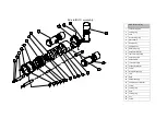
Страница 25: ...lister body 7 camera body 8 PCB fixing ring 9 horizontal thruster 10 rear cover assembly 11 float fixing stud 12 cable clamp 13 vertical thruster 14 horizontal thruster 15 screw 16 thruster mounting 1...

Страница 26: ...5 back cover 36 back cover retaining ring 37 sealing ring 38 vertical thruster mounting 39 sealing ring 40 cable pressure seal 41 sealing ring fastening 42 cable pressure seal bush 43 washer 44 screw...

Страница 27: ...ring 65 thruster rod 66 thruster 67 motor mounting washer 68 thruster mounting washer 69 thruster tube 70 sealing ring 71 thruster closure backwall 72 sealing ring 73 light port 74 sealing ring 75 clo...

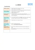
Страница 28: ...hard clean slide bearing of propeller coupling axis and check the coupling setting Underwater unit does not respond correctly to Joystick You have probably switched the function MAKRO on joystick on s...

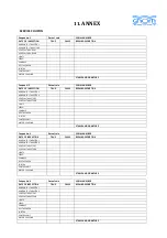
Страница 29: ...VERTICAL THRUSTER B LIGHTS SERVO COMPASS DEPTH SENSOR JOYSTICK CONTROL UNIT MOTOR COUPLING STAMP AND SIGNATURE Coupon No 3 Date of sale SERIAL NUMBER DATE OF INSPECTION TRUE FALSE REPAIR DESCRIPTION...

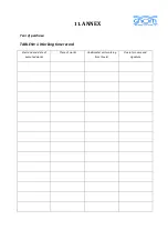
Страница 30: ...11 ANNEX Year of purchase TABLE 1 Working time record Start and end date of executed works Place of works Underwater unit working time hours Operator name and signature...

Страница 31: ...d parameter of network fuse Type and parameter of power cable fuse 180V Operator name and work position Signature 1 2 3 4 5 Table No 3 Inspection of coaxial cable intactness Date Type of cable Result...

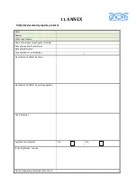
Страница 32: ...yee accepting the complaint Date of accepting the complaint Date of product sale Type of product serial number Description of defect by client Description of defect by service operator Used material L...

Отзывы: