Rev. 5.7.2019
TCD MANUAL
Copyright 2019 Vestil Manufacturing Co.
Page 9 of 20
Power unit operation
NOTE:
If your trash can dumper was manufactured on or after 12/01/2018, it is equipped with a 2
nd
generation
modular power unit (MPU-GEN2). Pages 9-14 of this manual are replaced by separate MPU-GEN2 manuals.
Powered functions are controlled by a modular, electric-hydraulic power unit. Control signals from the power unit
either extend or retract a hydraulic cylinder. Cylinder extension lifts the chute. Retraction lowers the chute, i.e. returns
it to home position. An electric motor directly coupled to a gear pump pressurizes the hydraulic system. The hydraulic
control components are housed inside a manifold bolted to the gear pump. All components are rated for 3,000psi
working pressure.
Noteworthy components of the power unit include:
•
Electric motor: the motor is either AC powered (wall socket) or DC powered (battery). AC-powered motors can be
wired for either single-phase or three-phase operation. Every motor is dual-voltage capable.
•
Gear pump: the pump shaft is directly coupled to the shaft of the electric motor. Several displacements are
available to match the horsepower of the motor selected.
•
Check valve: prevents backflow of fluid through the pump and to the reservoir. Because fluid can only flow in
response to an electrical signal from the pendant controller, the chute can maintain any position between the
raised and lowered configurations.
•
Pressure relief valve: opens a path for fluid to flow back to the reservoir if fluid pressure exceeds 3,000psi.
•
Lowering solenoid valve: electrically-operated cartridge valve with an integral screen to keep contaminants from
entering the valve.
•
Pressure compensated flow control spool: this device regulates the flow of hydraulic oil from the cylinder back to
the reservoir. It is located beneath the lowering valve. This component allows the table to lower at a
predetermined constant rate regardless of the weight of the dumper and contents. Several sizes are available.
•
Displacement style hydraulic cylinder: each cylinder includes a bleeder valve located at top end for removing air
from the hydraulic system.
•
Velocity fuse: a safety device installed in the hose port of each cylinder. If a hose is punctured while the unit is
operating, the velocity fuse closes and the chute remains stationary until pressure is reapplied to the system.
•
Hydraulic fluid: HO150 hydraulic fluid. To replenish the fluid, add anti-wear hydraulic fluid with a viscosity grade of
150 SUS at 100°F (ISO 32 @ 40°C) like AW-32 or Dexron transmission fluid.
Raising and lowering the chute
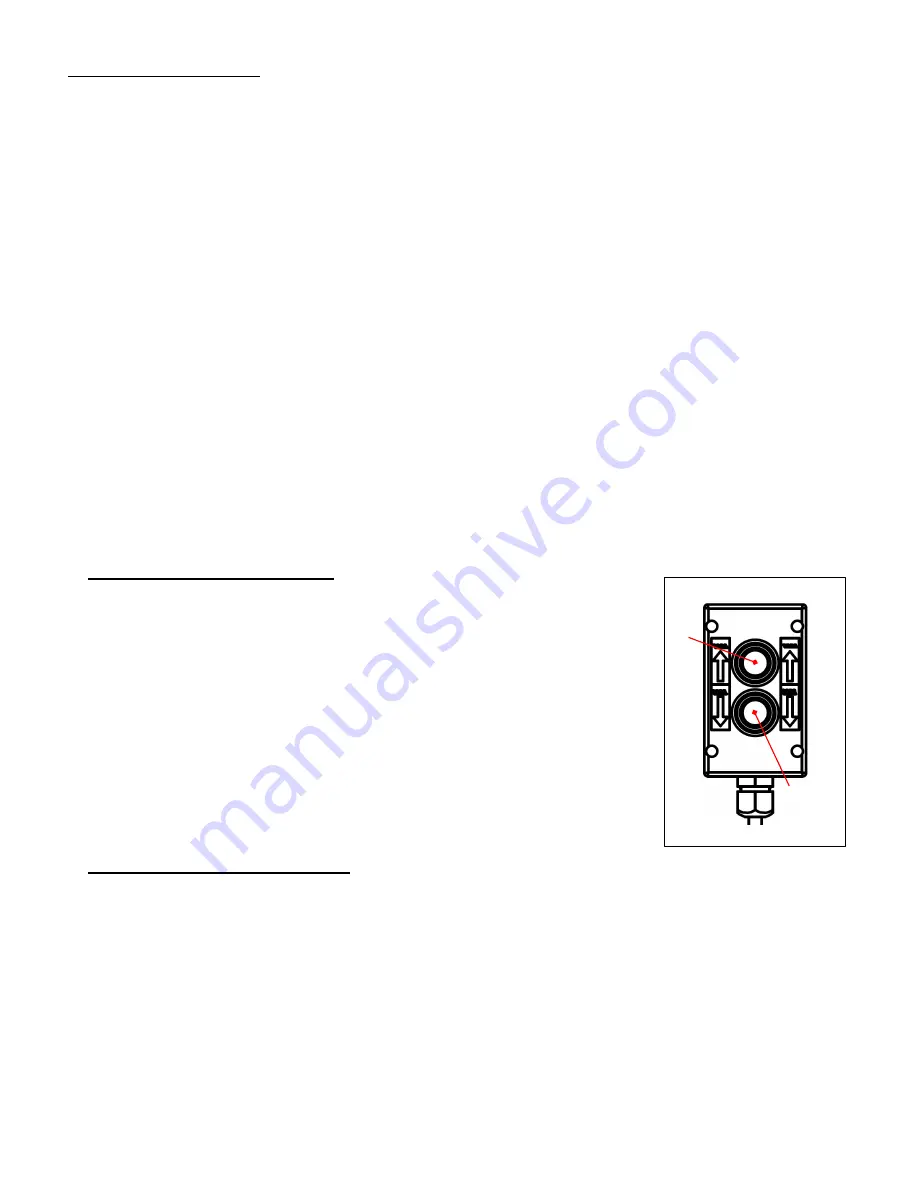
To raise/tilt the chute, hold the hand control and press the UP button. In response,
the motor turns and rotates the gear pump. As the pump rotates, oil is drawn from the
reservoir, passes through the suction filter, and enters the pump.
•
The gear pump propels oil through the check valve to the lift cylinder.
•
Releasing the UP button during operation immediately halts chute movement.
Additionally, an electrical upper travel limit switch automatically turns off the motor
when the chute reaches a 45° angle to the ground (horizontal).
To lower the chute, press the DOWN button.
•
Lowering valve opens which bypasses the check valve and allows oil in the cylinder
to flow to the reservoir (through return hoses). Oil flow to the reservoir is regulated by
the pressure compensated flow control valve. By regulating the volume of oil that can
flow through the spool, the speed at which the chute lowers is kept constant.
•
Releasing the DOWN button during operation causes all chute movement to stop.
The chute will remain in the same position until you press either button on the
pendant controller.
Cleaning lowering solenoid valve
If the chute slowly loses elevation without pressing the DOWN button, lower the chute completely. Then, remove,
inspect, and clean the lowering cartridge valve in the following manner:
1. Lower the chute completely and turn off electrical power to the unit. If your dumper is AC powered, unplug the
electrical cord from the wall socket. If your unit is DC powered (battery), turn the key switch to the OFF position.
2. Unload the dumper.
3. Remove the nut that fastens the solenoid coil to the valve stem; then remove the coil and unscrew the valve
from the manifold.
4. Inspect the valve for blockage.
5. Inspect O-rings and back-up washers for cuts, tears, etc.
6. Submerge the valve in mineral spirits or kerosene.
7. Use a thin tool, such as a small screwdriver or a hex wrench, to push the poppet in and out several times from
the bottom end of the valve. The valve should move freely, about 1/16” between the closed and open positions.
If the poppet sticks, the valve stem might be bent. Replace the poppet if it doesn’t free up after cleaning.
8. Remove mineral oil from the valve with compressed air.
9. Move the poppet in and out.
UP
DOWN
HAND CONTROL


