


Vertiv
|
NetSure™ 2100 Series -48 VDC Power System Installation Manual (IM582138000)
|
Rev. C
13
INSTALLING THE SYSTEM
General Requirements
NOTE!
The system is furnished for 19” mounting as standard. For 23” mounting, replace the 19”
mounting brackets on the shelf with the 23” mounting brackets (supplied with the system). A wall
mounting option is also available. See SAG582138000 for ordering information.
•
The installer should be familiar with the installation requirements and techniques to be used in securing
the relay rack (if furnished) to the floor.
•
The installer should be familiar with the installation requirements and techniques to be used in securing
the system to a relay rack or equipment rack.
-
The top rear cover needs to be removed to access the battery and/or CO ground connection points.
If other equipment is mounted above the shelf, leave enough clearance to access the screws
securing the cover.
•
The installer should be familiar with the installation requirements and techniques to be used in securing
the system to a suitable wall (if required).
•
This product is intended only for installation in a restricted access location on or above a non-
combustible surface.
•
This product must be located in a controlled environment with access to crafts persons only.
•
This product is intended for installation in network telecommunication facilities (CO, vault, hut, or other
environmentally controlled electronic equipment enclosure).
•
This product is intended for connection to the common bonding network in a network
telecommunication facility (CO, vault, hut, or other environmentally controlled electronic equipment
enclosure).
•
The DC return connection to this system can remain isolated from system frame and chassis (DC-I).
•
This system is suitable for installation as part of the Common Bonding Network (CBN).
•
The system must be mounted in an environment that does not exceed the rated operating ambient
temperature range found in SAG582138000.
•
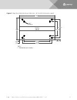
Clearance requirements are (relay rack or equipment rack):
-
Minimum clearance is one inch from the face of the rectifier modules and one inch from the surface
of the rear sheet metal (for ventilation only; operation, installation and maintenance require more
clearance).
-
Recommended minimum aisle space clearance for the front of each bay is 2' 6"
(for operation and maintenance).
-
Recommended minimum aisle space clearance for the rear of each bay is 2’ 0”
(for installation and maintenance).
-
List AA and CA: No space required above or below the unit (for ventilation only, installation and
maintenance may require more clearance).
-
List BA and BB: Space is required above or below the unit (for ventilation only, installation and
maintenance may require more clearance).


