background image

6

1 PSI5 Description

Vertiv™ | Liebert® PSI5 120 V Input / 120 V Output & 208 V lnput / 208 V Output Installer/User Guide

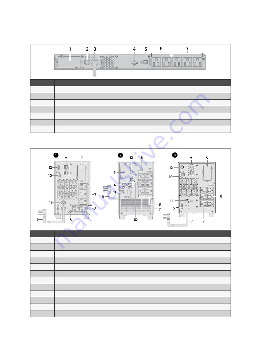
Figure 1-5 Liebert® PSl5-1000/1500RM1201U Rear Panel

ITEM

DESCRIPTION

1

IntelliSlot Port

2

Input Circuit Breaker (13A, 16A for 1000RM and 1500RM models respectively)

3

AC Input

4

Emergency Power Off (EPO) Connector

5

USB Port

6

Programmable Receptacles

7

Non-Programmable Receptacles

Figure 1-6 Liebert® PSI5 Mini Tower Rear Panels

ITEM

DESCRIPTION

1

PSI5-750/1100MT120

2

PSI5-1500MT120

3

PSI5-1500MT120LI

4

Network/Fax/Modem Surge Protection Input/Output

5

Grounding Screw for Network/Fax/Modem Surge Protection Input/Ouptut (Torque = 7 lbf-in)

6

IntelliSlot Port

7

Non-Programmable Receptacles

8

Programmable Receptacles

9

AC Input

10

USB Port

11

AC Input Breaker (10A, 13A, 16A for 750MT, 1100MT, 1500MT models respectively)

12

Emergency Power Off (EPO) Connector

Содержание LIEBERT PSI5 Series

Страница 1: ...Liebert PSI5 120V Input 120V Output 208V lnput 208V Output Installer User Guide ...

Страница 2: ...o other local practices or building codes as applicable for the correct methods tools and materials to be used in performing procedures not specifically described in this document The products covered by this instruction manual are manufactured and or sold by Vertiv This document is the property of Vertiv and contains confidential and proprietary information owned by Vertiv Any copying use or disc...

Страница 3: ... for installation 10 2 3 1 Installation Environment 10 2 3 2 Installation Clearances 10 2 4 Installing the UPS 10 2 4 1 Installing a 2U Model 10 2 4 2 Installing a 1U Model 13 2 4 3 Installing a Mini Tower MT Model 14 2 5 Connecting Loads 14 2 6 Connecting for Network Protection optional 14 2 7 USB Connection 14 2 8 Emergency Power Off EPO Connection Optional 14 2 9 External Battery Cabinet Connec...

Страница 4: ...R Buck Mode 17 3 1 5 On Battery Mode 17 3 1 6 Fault Mode 17 3 1 7 Battery Self Test Mode 17 3 1 8 Controls 18 3 2 Display Panel Indicators 19 3 3 Audible Tone Indicators 21 3 4 Warnings 21 3 5 Faults 22 3 6 Normal Startup 22 3 7 Normal Shutdown 23 3 8 Full Shutdown 23 3 9 Configuring UPS with the Settings Menu 23 4 Maintenance and Battery Replacement 27 4 1 Precautions 27 4 2 Battery Charging 27 4...

Страница 5: ...on IMPORTANT This manual contains important safety instructions that must be followed during the installation and maintenance of the UPS and batteries Read this manual thoroughly and the safety and regulatory information available at https www vertiv com ComplianceRegulatoryInfo before attempting to install connect to supply or operate this UPS ...

Страница 6: ...2 Important Safety Information Vertiv Liebert PSI5 120V Input 120V Output 208V lnput 208V Output Installer User Guide This page is intentionally left blank ...

Страница 7: ...els The optional Liebert Network Communication Card makes advanced monitoring and control available 1 1 Available Models Table 1 1 PSI5 Models BATTERY TYPE MODEL FORM FACTOR MODEL NUMBER NOMINAL POWER RATING 120V INPUT VRLA Valve Regulated Lead Acid 2U PSI5 800RT120 800 VA 720 W PSI5 1100RT120 1100 VA 990 W PSI5 1500RT120 1500 VA 1350 W PSI5 1500RT120TAA PSI5 2200RT120 1920 VA 1920 W PSI5 2200RT12...

Страница 8: ...rammable Receptacles 6 Non Programmable Receptacles 7 IntelliSlot Port 8 Emergency Power Off EPO Connector 9 Input Circuit Breaker 10A 13A 16A for 800RT 1100RT 1500RT models respectively 10 AC Input Figure 1 2 Liebert PSI5 2200RT120 PSI5 2200RT120TAA PSI5 2200RT120LI Rear Panel ITEM DESCRIPTION 1 Grounding Screw for Network Fax Modem Surge Protection Input Ouptut Torque 7 lbf in 2 Network Fax Mode...

Страница 9: ...n LI models 4 USB Port 5 Programmable Receptacles 6 Non Programmable Receptacles 7 IntelliSlot Port 8 Emergency Power Off EPO Connector 9 Input Circuit Breaker 30A 10 AC Input 11 Output Circuit Breaker Figure 1 4 Liebert PSl5 5000RT208 Rear Panel ITEM DESCRIPTION 1 Grounding Screw for Network Fax Modem Surge Protection Input Ouptut Torque 7 lbf in 2 Network Fax Modem Surge Protection Input Output ...

Страница 10: ...rt 6 Programmable Receptacles 7 Non Programmable Receptacles Figure 1 6 Liebert PSI5 Mini Tower Rear Panels ITEM DESCRIPTION 1 PSI5 750 1100MT120 2 PSI5 1500MT120 3 PSI5 1500MT120LI 4 Network Fax Modem Surge Protection Input Output 5 Grounding Screw for Network Fax Modem Surge Protection Input Ouptut Torque 7 lbf in 6 IntelliSlot Port 7 Non Programmable Receptacles 8 Programmable Receptacles 9 AC ...

Страница 11: ... and Display on 2U and MT Models ITEM DESCRIPTION 1 ON MUTE button See Controls on page 18 for details 2 SELECT button See Controls on page 18 for details 3 OFF ENTER button See Controls on page 18 for details Figure 1 8 Controls and Display on 1U Models ITEM DESCRIPTION 1 ON MUTE button See Controls on page 18 for details 2 SELECT button See Controls on page 18 for details 3 OFF ENTER button See ...

Страница 12: ...8 1 Vertiv Liebert PSI5 120 V Input 120 V Output 208 V lnput 208 V Output Installer User Guide This page is intentionally left blank ...

Страница 13: ... x Rack ear screws M4 x 8 mm USB type A to B cable Rail slide kit box Left and right rail set 8 x Rail kit screws M6 x 12 mm 4 x Fixing studs Ø8 5 mm x 15 5 mm 6 x Rack nuts M6 NEMA L5 20R to 5 20P adapter cord 2200RT models only RM models UPS Accessory box including Quick installation guide Safety Instructions 2 x UPS rack ears 8 x Rack ear screws M4 x 8mm USB type A to B cable Rail slide kit box...

Страница 14: ...ions listed Specifications on page 31 Place it in an area of unrestricted airflow around the unit away from water flammable liquids gases corrosives and conductive contaminants Avoid direct sunlight The socket outlet should be nearby and easily accessible NOTE Operating the UPS in temperatures above 77 F 25 C reduces battery life 2 3 2 Installation Clearances Maintain at least 4 in 100 mm clearanc...

Страница 15: ...r orientation 2 Connect the two halves of the stand together 3 Place the UPS in the stands 4 Make sure that the stands are installed 70mm 2 76 in form the edge of the unit Figure 2 2 Attaching stands to the UPS and external battery ITEM DESCRIPTION 1 Insert a spacer on each stand and install the securing screws 2 Connect the two halves of the stand together and install the securing screws 3 Place ...

Страница 16: ...ears with four rack ear screws to the front right and left sides of the UPS 2 Attach two fixing studs to each rail Select the desired U position and position the rails onto the rack using the fixing studs 3 Attach two rail kit screws to each rail to secure the rails to the rack 4 Attach three rack nuts on each side of the rack 5 Place the UPS with attached rack ears onto the rail supports The batt...

Страница 17: ...lling a 1U Model CAUTION Do not use the mounting brackets to lift the unit Use the mounting brackets only to secure the UPS to the rack See Figure 2 5 below to install the unit Figure 2 5 Installing the UPS in a rack ITEM DESCRIPTION 1 Attach the rack ears with four rack ear screws to the front right and left sides of the UPS 2 Attach two fixing studs to each rail Select the desired U position and...

Страница 18: ...ailure can be done using the Liebert Power Assist software via the USB port Visit www vertiv com powerassist for additional information 2 8 Emergency Power Off EPO Connection Optional To comply with national and local wiring codes and regulations the EPO connector internally disconnects all power sources to equipment connected to the UPS The default operation is active open which means you must re...

Страница 19: ...nets are used with PSI5 1100 2200 3000 5000 models the UPS load rating is decreased by 20 Figure 2 6 Connecting External Batteries ITEM DESCRIPTION 1 Connection to UPS 2 Connection from UPS to single first external battery 3 Connection to second connector on external battery cabinet for additional battery cabinets 4 Connect to next external battery 2 10 Network Communication Card Connection Option...

Страница 20: ...cations on page 31 for input cord rating An external circuit breaker as described in Table 2 1 below is recommended Once the UPS is plugged into the wall outlet it begins charging the battery NOTE While every precaution has been taken to ensure that the battery is in good condition VertivTM recommends plugging the UPS into AC input and to charge the battery for at least 12 hours prior to providing...

Страница 21: ...uck Mode The UPS input is plugged in but the voltage source is abnormally high The UPS automatically corrects the high voltage and allows the outlets to be on with the normal expected voltage The internal batteries are charging 3 1 5 On Battery Mode The UPS input is not plugged in or the voltage source has become extremely low or high and unusable The UPS automatically switches to the internal bat...

Страница 22: ...n Battery mode press and hold for 3 seconds Settings Menu UP When in the Settings Menu press to cycle up through options See Configuring UPS with the Settings Menu on page 23 2 SELECT Button Select Press to cycle through the operating parameters Settings Menu When in Off mode press and hold for 3 seconds to enter the Settings Menu Settings Menu Down When in Settings Menu press to cycle down throug...

Страница 23: ... to wake the display Figure 3 1 on page 18 shows the LCD on the front panel of the UPS Table 3 2 Display icons sections and functions ICONS AND DISPLAY DESCRIPTION Off mode On Normal mode On AVR Boost mode On AVR Buck mode On Battery mode Estimated backup time in H hours M minutes or S seconds Indicates warning and fault codes See Faults on page 22 and Warnings on page 21 Displays various UPS oper...

Страница 24: ...er Guide ICONS AND DISPLAY DESCRIPTION Settings menu See Configuring UPS with the Settings Menu on page 23 Audible On Battery mode alarm silenced UPS output load in 25 increments Battery level in 25 increments Low battery Overload icon Programmable outlet icon Battery icon Battery charging icon ...

Страница 25: ...utputs are shut off Table 3 4 Warning Indicators and Actions ITEM DESCRIPTION TROUBLESHOOTING Battery low Charge the UPS battery for at least 12 hours or replace the battery see Replacing the UPS Batteries on page 27 Overload Reduce the load to below the rating indicated in the Specifications on page 31 Site wiring fault Turn of the UPS and call an electrician to correct the wiring Possible causes...

Страница 26: ...2 5877 02 Bus over 03 Bus under 11 Inverter soft start fail 12 Inverter voltage high Turn Off the UPS disconnect all connected loads and restart the UPS If the fault is still active call Vertiv customer support 1 800 222 5877 If the fault is no longer active plug each piece of equipment in one at a time to locate the device that has the short circuit 13 Inverter voltage low 14 Inverter output shor...

Страница 27: ...n to configure and the second lists the selectable parameters for each setting option Table 3 6 describes the setting options In addition symbols relevant to the setting option may be shown The symbols are described in Table 3 2 on page 19 Figure 3 3 UPS Display In Setting Mode ITEM DESCRIPTION 1 Setting option number 2 Setting parameter To access Settings mode and adjust settings 1 Power off the ...

Страница 28: ...ng a shorter time limit for programmable outlets extends the time the non programmable outlets are powered when running on battery O to 999 minutes 999 is defauIt 04 Enable Disable site fault detection ENA Enable default DIS Disable 05 Enable Disable neutral grounding in battery mode ENA Enable default DIS Disable 06 Battery backup time limit Sets a maximum time to provide output when running on b...

Страница 29: ...ger battery life and run times ST1 High sensitivity default Provides the maximum protection The transfer time is typically 4 to 6 ms 10ms max ST2 Medium sensitivity Provides medium protection The transfer is typically 6 to 8 ms 11 ms max ST3 Low sensitivity Provides the least protection but may provide longer battery life and run time for tolerant equipment The transfer time is typically 8 to 10 m...

Страница 30: ...26 3 Operation Vertiv Liebert PSI5 120V Input 120V Output 208V lnput 208V Output Installer User Guide This page is intentionally left blank ...

Страница 31: ...batteries The Lithium Ion batteries used in the PSI5 LI series as well as all Vertiv Lithium Ion UPSs contain a Battery Management System BMS that self monitors the safety of the LI batteries in real time This is an agency tested and certified requirement now eliminating the industry wide safety risk known with previous Li Ion batteries 4 3 Replacing the UPS Batteries IMPORTANT Before you proceed ...

Страница 32: ...e the Battery Self Check mode clearing any previous battery fault warning 11 Properly dispose of the old batteries at an appropriate recycling facility or return them to Vertiv in the packing material from the new batteries Figure 4 1 Removing the battery box from 2U units to replace batteries ITEM DESCRIPTION 1 Remove the front panel from the UPS 2 Disconnect the battery connector by squeezing th...

Страница 33: ... unit on its left side and remove the 6 screws and the metal battery cover plate 2 SIide out the existing battery kit and disconnect the two halves of the battery connector 3 For LI models attach the provided connector to the replacement battery terminals Plug the black wire in first then the red For VRLA models skip this step 4 Orient the connector and the new battery in the same way as the origi...

Страница 34: ...on MT models ITEM DESCRIPTION 1 With unit laying on left side remove screws from battery cover 2 Remove the battery cover 3 Slide out the battery kit and disconnect the battery connector 4 Connect the battery connector to the replacement battery 5 Slide the replacement battery kit into the UPS 6 Replace the battery cover 7 Secure the battery cover with the screws ...

Страница 35: ...A 1600 W 16 A 2400 VA 2400 W 24 A 240 VAC Input 5000 VA 4500 W 20 8 A 230 VAC Input 5000 VA 4500 W 21 7 A 220 VAC Input 5000 VA 4500 W 22 7 A 208 VAC Input 4250 VA 3825 W 20 4 A 200 VAC Input 4250 VA 3825 W 21 3 A Dimensions and Weights Unit Dimensions W x D x H in mm 17 2 x 16 1 x 3 5 438 x 410 x 88 17 2 x 20 0 x 3 5 438 x 510 x 88 17 2 x 24 8 x 3 5 438 x 630 x 88 Shipping Dimensions W x D x H in...

Страница 36: ...set 90 degree type 3 m attached NEMA L5 20P 3 m attached NEMA L5 20 to 5 20P adapter cord 150 mm NEMA L5 30P 3 m attached NEMA L6 30P 3 m attached Output Output Voltages on battery 100 110 115 120 125 VAC 1 5 on battery before alarm user selectable 120 VAC is factory default 200 208 240VAC 1 5 on battery before alarm user selectable 208 VAC is factory default Output Frequency on battery 60 default...

Страница 37: ...BATTTAA Protection Circuit Breaker Type Valve regulated lead acid VRLA in compliance with UL 1989 Quantity x Voltage x Ah 2 x 12V x 9 0 Ah 2 x 12V x 9 0 Ah 4 x 12V x 9 0 Ah 4 x 12V x 9 0 Ah 6 x 12V x 9 0 Ah 6 x 12V x 9 0 Ah Unit Dimensions W x D x H in mm 17 2 x 16 1 x 3 5 438 x 410 x 88 17 2 x 20 x 3 5 438 x 510 x 88 17 2 x 24 8 x 3 5 438 x 630 x 88 Shipping Dimensions W x D x H in mm 10 2 x 22 9...

Страница 38: ... 220 Shipping Dimensions W x D x H in mm 22 4 x 27 6 x 6 5 570 x 700 x 165 22 4 x 29 9 x 6 5 570 x 760 x 165 9 1 x 17 7 x 12 8 230 x 450 x 325 9 1 x 22 4 x 12 8 230 x 570 x 325 Unit Weight lb kg 36 4 16 5 45 6 20 7 24 7 11 2 26 0 11 8 40 1 18 2 Shipping Weight lb kg 42 3 19 2 52 2 23 7 27 8 12 6 29 1 13 2 44 1 20 0 Input Voltage Input Range with battery operation 0 to 150 VAC Voltage Input Range w...

Страница 39: ...d immediate shutdown Protection Electronic overcurrent short circuit w latching shutdown AC Mode Efficiency 98 96 Buck and Boost Mode Efficiency 93 Recharge Time 6 hours to recover to 90 6 8 hours to recover to 90 Internal Battery Part Number PSI5 10001UBATKIT PSI5 15001UBATKIT PSI5 750MTBATKIT PSI5 1100MTBATKIT PSI5 1500MTBATKIT Protection Electronic overcurrent short circuit with latching shutdo...

Страница 40: ...x 22 4 258 x 672 x 570 10 2 x 26 7 x 22 4 258 x 782 x 570 9 1 x 19 5 x 12 8 230 x 495 x 325 Unit Weight lb kg 28 4 12 9 39 7 18 0 53 6 24 3 28 0 12 7 Shipping Weight lb kg 42 1 19 1 53 8 24 4 67 9 30 8 31 2 14 2 Input Voltage Input Range with battery operation 0 to 150 VAC Voltage Input Range without battery operation 75 to 146 VAC Input Voltage Measurement Tolerance 3 Nominal Voltage Setting 100 ...

Страница 41: ...seconds 120 Alarm warning and immediate shutdown Protection Electronic overcurrent short circuit w latching shutdown AC Mode Efficiency 97 Buck and Boost Mode Efficiency 94 Recharge Time typical 2 hours to recover to 100 2 hours to recover to 100 3 hours to recover to 100 2 hours to recover to 100 Internal Battery Part Number PSI5 1500LIBATKIT PSI5 2200LIBATKIT PSI5 3000LIBATKIT PSI5 1500LIBATKIT ...

Страница 42: ...118 160 202 246 60 480 432 12 5 51 96 144 193 244 295 50 400 360 16 2 64 119 178 239 300 363 40 320 288 21 7 84 155 230 306 384 462 30 240 216 30 5 116 213 313 415 517 620 20 160 144 44 4 167 303 441 581 721 862 10 80 72 85 6 313 552 79 2 1034 1276 1519 Table 5 5 PSI5 1100RT120 LOAD NUMBER OF EXTERNAL BATTERY CABINETS LOAD NUMBER OF EXTERNAL BATTERY CABINETS INTERNAL BATTERY ONLY 1 2 3 4 5 6 VA W ...

Страница 43: ...6 651 807 964 10 150 135 110 9 198 695 994 1294 1594 1895 Table 5 7 PSI5 2200RT120 PSI5 2200RT120TAA LOAD NUMBER OF EXTERNAL BATTERY CABINETS LOAD NUMBER OF EXTERNAL BATTERY CABINETS INTERNAL BATTERY ONLY 1 2 3 4 5 6 VA W MINUTES VA W MINUTES 100 1920 1920 4 9 27 100 1536 1536 72 111 152 194 237 90 1728 1728 5 9 32 90 1382 4 1382 83 127 174 222 270 80 1536 1536 7 2 37 80 1228 8 1229 96 147 201 255...

Страница 44: ... 864 168 245 324 404 484 30 576 810 32 2 101 30 720 648 233 338 444 551 658 20 384 540 46 3 145 20 480 432 327 470 613 758 902 10 192 270 103 2 313 10 240 216 653 923 1195 1466 1738 Table 5 9 PSI5 5000RT208 LOAD NUMBER OF EXTERNAL BATTERY CABINETS LOAD NUMBER OF EXTERNAL BATTERY CAB INETS INTERNAL BATTERY ONLY 1 2 3 4 5 6 VA W MINUTES VA W MINUTES 100 4250 3825 3 15 100 4000 3600 30 45 60 76 93 90...

Страница 45: ...00 900 5 1 90 900 810 5 8 80 800 720 6 9 70 700 630 8 3 60 600 540 10 4 50 500 450 13 4 40 400 360 18 2 30 300 270 26 9 20 200 180 41 9 10 100 90 90 6 Table 5 11 PSI5 1500RM1201U LOAD MINUTES VA W 100 1500 1350 5 1 90 1350 1215 5 9 80 1200 1080 7 1 70 1050 945 8 5 60 900 810 10 6 50 750 675 13 5 40 600 540 18 4 30 450 405 26 9 20 300 270 41 6 10 150 135 91 2 ...

Страница 46: ...0 675 6 1 90 675 607 5 7 3 80 600 540 8 8 70 525 472 5 10 9 60 450 405 13 8 50 375 337 5 17 7 40 300 270 23 5 30 225 202 5 33 0 20 150 135 48 0 10 75 67 5 92 5 Table 5 13 PSI5 1100MT120 LOAD MINUTES VA W 100 1100 990 4 6 90 990 891 5 6 80 880 792 6 8 70 770 693 8 5 60 660 594 11 0 50 550 495 13 7 40 440 396 18 8 30 330 297 27 5 20 220 198 45 5 10 110 99 107 0 ...

Страница 47: ...0 6 3 90 1350 1215 7 5 80 1200 1080 9 1 70 1050 945 11 2 60 990 810 14 1 50 750 675 18 1 40 600 540 24 2 30 450 405 34 2 20 300 270 50 4 10 150 135 110 9 Table 5 15 PSI5 1500RT120LI LOAD MINUTES VA W 100 1500 1350 7 5 90 1350 1215 8 9 80 1200 1080 10 3 70 1050 945 12 1 60 900 810 14 6 50 750 675 17 7 40 600 540 22 8 30 450 405 30 6 20 300 270 45 3 10 150 135 89 0 ...

Страница 48: ... 6 90 1728 1728 9 9 80 1536 1536 11 5 70 1344 1344 13 5 60 1152 1152 16 1 50 960 960 19 0 40 768 768 24 5 30 576 576 33 2 20 384 384 48 1 10 192 192 93 6 Table 5 17 PSI5 3000RT120LI LOAD MINUTES VA W 100 3000 2700 8 9 90 2700 2430 10 5 80 2400 2160 11 9 70 2100 1890 13 9 60 1800 1620 16 5 50 1500 1350 20 0 40 1200 1080 25 5 30 900 810 34 2 20 600 540 49 1 10 300 270 96 6 ...

Страница 49: ...tput 208V lnput 208V Output Installer User Guide Table 5 18 PSI5 1500MT120LI LOAD MINUTES VA W 100 1500 1350 7 5 90 1350 1215 8 9 80 1200 1080 10 3 70 1050 945 12 1 60 900 810 14 6 50 750 675 17 7 40 600 540 22 8 30 450 405 30 6 20 300 270 45 3 10 150 135 89 0 ...

Страница 50: ...46 5 Specifications Vertiv Liebert PSI5 120 V Input 120 V Output 208 V lnput 208 V Output Installer User Guide This page is intentionally left blank ...

Страница 51: ...tiv Liebert PSI5 120V Input 120V Output 208V lnput 208V Output Installer User Guide http www facebook com Vertiv http www instagram com Vertiv http www linkedin com company Vertiv http www twitter com Vertiv ...

Страница 52: ...red trademarks of their respective owners While every precaution has been taken to ensure accuracy and completeness here Vertiv Group Corp assumes no responsibility and disclaims all liability for damages resulting from use of this information or for any errors or omissions Specifications rebates and other promotional offers are subject to change at Vertiv s sole discretion upon notice SL 23314_RE...

Отзывы: