


2.7.3 Normal Mode Start-Up
1. Close the external output MCB and input MCB of the UPS one by one. If the single POD is selected
to connect with the UPS
,
close the input MCB, bypass MCB and output MCB of the POD.
A
After closing the UPS external output MCB or the POD output MCB, the output terminal block of the UPS,
output terminal block of the POD and power distribution end of the load will be live, pay attention to
personal safety to avoid electric shock. Note whether it is safe to feed power to the load.
2. The rectifier runs in normal state for about 30 seconds
,
the start-up of the rectifier is finished.
3. Finish and check the parameter settings of the single UPS.
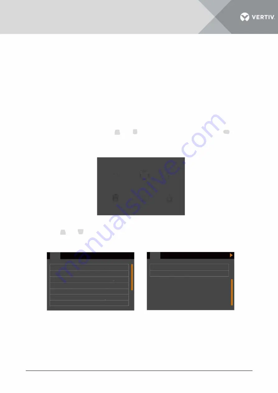
a) At main menu screen
, p
ress the
E!I
or
B
key to select 'Settings', and press the
Ill
key
to enter the interface shown in Figure 2-33.
0
0
'
Status
Settings
Control
i
..l.
"
Log
About
Maintain
Figure 2-33
Main menu screen
b) Press the
E!I
or
�
key to select and set corresponding parameters (taking 'Output' as an
example) as shown in Figure 2-34.
Output
Battery
Voltage selection
Startup on bypass Frequency
selection Inverter sync range
Bypass voltage upper limit
Bypass voltage lower limit
Bypass frequency range
Parallel
230V
Disable
Auto,Byp
+20%
-40%
+ 10%
Figure
2-34
Vertiv I Liebert
®
IT A2
™
5kVA ~ 20kVA UPS I User Manual
►
Output
Run mode
Output phase No
Battery
Output interface
Parallel
Normal
3phase
45
Содержание Liebert ITA2
Страница 1: ...5 20 kVA User Manual...
Страница 2: ......
Страница 3: ......
Страница 4: ......
Страница 5: ......
Страница 6: ...Vertiv disclaims any and all responsibility or liability for the defects or malfunction caused by...
Страница 7: ......
Страница 8: ......
Страница 9: ......
Страница 10: ...Product Model 5kVA 6kVA 10kVA 16kVA 20kVA...
Страница 15: ...1 Product Introduction The...
Страница 16: ......
Страница 17: ......
Страница 18: ......
Страница 19: ......
Страница 20: ......
Страница 21: ......
Страница 22: ......
Страница 23: ......
Страница 24: ......
Страница 25: ...Battery...
Страница 26: ......
Страница 27: ......
Страница 28: ......
Страница 29: ...2 SingleUPSInstallationAnd Commissioning...
Страница 30: ......
Страница 31: ......
Страница 32: ......
Страница 33: ......
Страница 34: ......
Страница 35: ......
Страница 36: ......
Страница 37: ......
Страница 38: ......
Страница 39: ......
Страница 40: ......
Страница 41: ......
Страница 42: ......
Страница 43: ......
Страница 44: ......
Страница 45: ......
Страница 46: ......
Страница 47: ......
Страница 48: ......
Страница 49: ......
Страница 50: ......
Страница 51: ......
Страница 52: ......
Страница 53: ......
Страница 54: ......
Страница 55: ......
Страница 56: ......
Страница 57: ......
Страница 58: ...BAT...
Страница 59: ......
Страница 61: ......
Страница 64: ...3 ParallelUPSInstallationAnd Commissioning...
Страница 65: ......
Страница 66: ......
Страница 67: ......
Страница 68: ......
Страница 69: ......
Страница 70: ......
Страница 71: ......
Страница 72: ......
Страница 73: ......
Страница 74: ......
Страница 75: ......
Страница 76: ......
Страница 77: ......
Страница 78: ......
Страница 79: ...4 Operation And Display Panel...
Страница 80: ......
Страница 81: ......
Страница 82: ......
Страница 83: ......
Страница 84: ......
Страница 85: ......
Страница 86: ......
Страница 87: ...Log 00 0 0 00 20 Outp ut Battery y test time Batte ry serie s Disc hg protr ct time Equa l Paral lel able Tem p...
Страница 88: ...Maintain...
Страница 89: ......
Страница 90: ......
Страница 91: ......
Страница 92: ......
Страница 93: ......
Страница 94: ......
Страница 95: ......
Страница 96: ......
Страница 97: ......
Страница 98: ......
Страница 99: ......
Страница 100: ...5 UPS Operation Instructions...
Страница 101: ......
Страница 102: ......
Страница 103: ...Confirm S Turn off UPS ol NO YES Log About Maintain...
Страница 104: ...with...
Страница 105: ......
Страница 106: ......
Страница 107: ...5 Press the key for several times to back to the main menu screen...
Страница 108: ......
Страница 109: ......
Страница 110: ......
Страница 111: ......
Страница 112: ......
Страница 113: ......
Страница 114: ......
Страница 117: ...4...
Страница 119: ......
Страница 120: ...7 Maintenance...
Страница 121: ......
Страница 122: ......
Страница 123: ...8 Options...
Страница 124: ......
Страница 125: ......
Страница 126: ......
Страница 127: ......
Страница 128: ......
Страница 129: ......
Страница 130: ......
Страница 131: ...The standard battery cabinets are listed in Table 8 8 Corresponding battery CSB Dimension Weight...
Страница 132: ......
Страница 133: ...9 Attachment...
Страница 134: ......
Страница 135: ...Appendix 1 LCD Parameters Setting...
Страница 136: ......
Страница 137: ......
Страница 138: ...Appendix 2Glossary...
Страница 139: ...Appendix 3 HazardousSubstances AndContent...


