Vertiv™ |
Liebert® EXM™ UPS 20-100kVA, 50/60Hz User Manual
|
11
2.5.2
Clearances
Provide at least the minimum clearance required by NEC on all sides of Liebert
®
EXM, including 36" (914mm) in
front, to permit routine tightening of power terminations within the UPS and free passage of personnel with the
door fully opened. Depending on the floor anchoring system used, up to 5" (127mm) may be required in the rear
of the UPS.
There are no ventilation grilles on the sides or back of the UPS.
Leave a minimum of 24 in. (610mm) between the top of the UPS frame and the ceiling to permit adequate air
circulation above the unit. Vertiv
™
recommends against using air conditioning or other systems that blow air onto
the top of the unit.
2.5.3
Floor Installation
If the Liebert
®
EXM is to be placed on a raised floor, the UPS should be mounted on a pedestal that will support
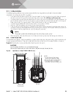
the equipment point loading. Refer to the bottom view in
2.5.4
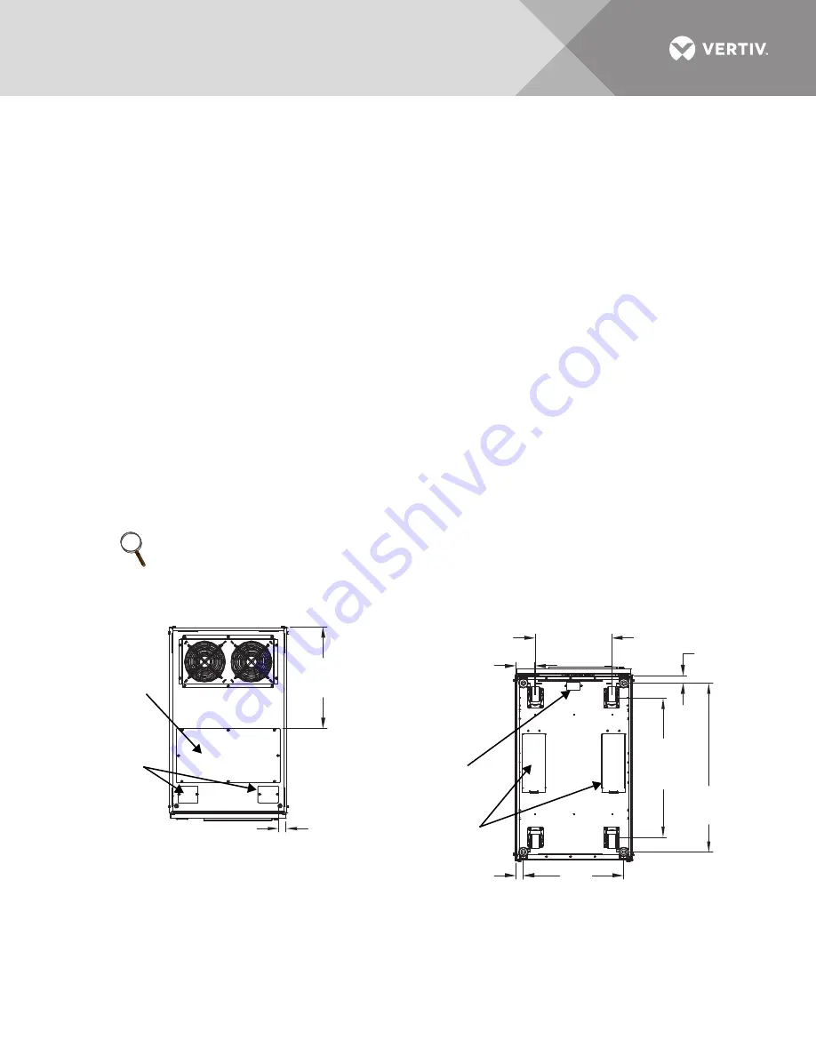
Cable Entry
Cables can enter the Liebert
®
EXM from the top or bottom through removable metal plates.
Some plates have factory-punched holes and others are designed to allow the personnel to punch holes for
fitting and securing the conduit. Once the conduit holes are punched, these plates should be reattached to the
UPS. The conduit size and wiring method must be in accordance with all local, regional and national codes and
regulations, including NEC ANSI/NFPA 70.
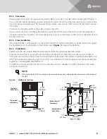
The UPS must be accessible from the front to allow personnel to complete the cable connections and make
necessary adjustments.
Figure 2
Cable entry locations
NOTE
When installing the UPS, the customer must provide a disconnect with overcurrent protection at the output of
the UPS.
20.6"
(523mm)
1.5"
(38mm)
TOP
20.4"
(518mm)
28.3"
(519mm)
Casters
15.6"
(396mm)
1.6"
(41mm)
1.6"
(41mm)
4"
(102mm)
34.3"
(872mm)
BOTTOM
Top Power
Cable Entry
Bottom Power
Cable Entry
Top Control
Cable Entry
Bottom Control
Cable Entry
Содержание Liebert EXM
Страница 1: ...Liebert EXM UPS User Manual 20kVA to 100kVA 208 120V 50 60Hz...
Страница 77: ......


