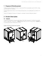


Vertiv™ XTE 802G Generator Room Walk-In-Cabinet Description and Installation Manual
11
2.7
Features and Options
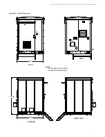
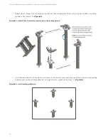
Perspective Views
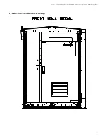
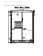
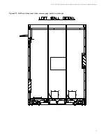
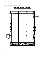
For illustrations of the XTE 802G, refer to the following.
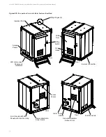
•
Refer to
for perspective views with major features identified.
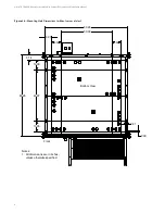
•
Refer to
•
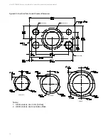
Refer to
for top view of floor; including floor cable entry ports locations.
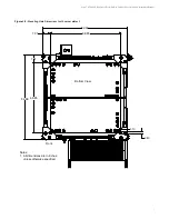
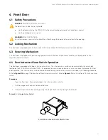
•
Refer to
for door intrusion switch location.
Construction
Welded galvanized steel construction with outstanding impact and corrosion resistance.
•
Interlocking steel panels construction.
•
Walls, floor and ceiling are made of 14 gauge steel.
•
Ceiling joists with 12 gauge steel.
•
Floor Load: 200 pounds per square foot minimum (uniform with full-support foundation).
•
Roof Live and Impact Load: 300 PSF (maximum).
•
Wind Speed: 180 mph.
Protection
Powder coat finish. Meets GR487 Telcordia mechanical and environmental standards for telecom cabinets.
•
Protects against rain, sleet, snow, splashing water and damage from external ice formation.
•
Optional exterior finishes including brick, stone and exposed aggregate are available upon request.
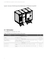
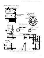
Mounting Base
Cable mounting base with 360 degree access to floor penetrations for easy conduit and cable entries into the XTE 802G Generator
Room. See
on page 8.
•
Fork lift tubes on left and right sides of cabinet.
•
Base includes steel cover plates front and back to accommodate cabling.
Common Equipment Kit
•
Interior -48 VDC Lights
•
Op24 VDC Smoke Detector
•
Door Contacts
•
Halo ground, interior isolated copper ground bar, H taps for ground terminal and external isolate ground bar, ground entry /
exit plate as per ATT grounding specification.


