4.1.9 External Protective Device
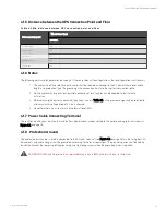
To ensure the safety, it is necessary to install external circuit breaker for the input and battery of the UPS. Because of the
difference of the specific installations, this section only provides general practical information for the installation engineer.
The qualified installation engineer should have the knowledge of the local wiring regulations on the equipment to be
installed.
Input power supply of rectifier and bypass
1.
Input overcurrent and short circuit protection
Install suitable protective devices in the distribution line of the incoming mains supply. The protective devices
should provide functions such as the overcurrent protection, short circuit protection, isolation protection, and
tripping upon backfeed. When selecting the protective devices, consider the power cable current-carrying
capacity, system overload capacity (see Table 12.6 on page 178 and Table 12.7 on page 179) and the short
circuit capability of the upstream power distribution.
Under the condition of adding external protective devices (use the recommended model or the device with
performance better than recommended model), the UPS can satisfy the requirement of KAIC.
2.
Split bypass configuration
If the UPS adopts split bypass configuration, independent protective device shall be installed respectively on
the rectifier input and bypass input distribution lines.
N O T E:
1. T h e rectifier in pu t an d bypass in pu t m u st u se th e sam e n eu tral lin e.
2. F o r IT grid system , 4-po le pro tective co m po n en ts m u st be in stalled fo r th e UP S extern al in pu t
po wer distribu tio n .
3.
Ground fault protection
If the upstream input power supply has an RCD, the transient state and steady state ground leakage current
upon the startup of the UPS shall be considered.
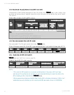
The RCCB shall meet the following requirements:
•
Be sensitive to the DC unidirectional pulse (class A) of the whole distribution network
•
Be insensitive to transient state current pulse
•
Have an average sensitivity which is 0.3 A to 3 A adjustable
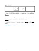
The RCCB symbols are shown in Figure 4.1 on the facing page.
4 Electrical Installation
36
Vertiv™ Liebert® APM Plus User Manual
Содержание APM 0250kMK16FN02000
Страница 1: ...Vertiv Liebert APM Plus User Manual 50 250 kVA UPS...
Страница 8: ...vi This page intentionally left blank Vertiv Liebert APM Plus User Manual...
Страница 16: ...1 Important Safety Instructions 8 This page intentionally left blank Vertiv Liebert APM Plus User Manual...
Страница 30: ...2 Overview 22 This page intentionally left blank Vertiv Liebert APM Plus User Manual...
Страница 60: ...4 Electrical Installation 52 This page intentionally left blank Vertiv Liebert APM Plus User Manual...
Страница 73: ...Figure 5 11 Customize the display 5 Operator Control and Display Panel 65 Vertiv Liebert APM Plus User Manual...
Страница 97: ...5 Operator Control and Display Panel 89 Vertiv Liebert APM Plus User Manual...
Страница 154: ...Figure 8 8 LBS port J4 on bypass control module 8 Parallel System and LBS System 146 Vertiv Liebert APM Plus User Manual...
Страница 182: ...11 Service and Maintenance 174 This page intentionally left blank Vertiv Liebert APM Plus User Manual...
Страница 188: ...12 Specifications 180 This page intentionally left blank Vertiv Liebert APM Plus User Manual...
Страница 191: ...Vertiv Liebert APM Plus User Manual...


