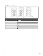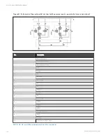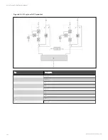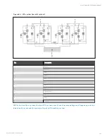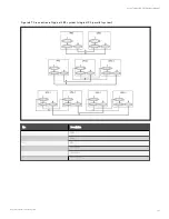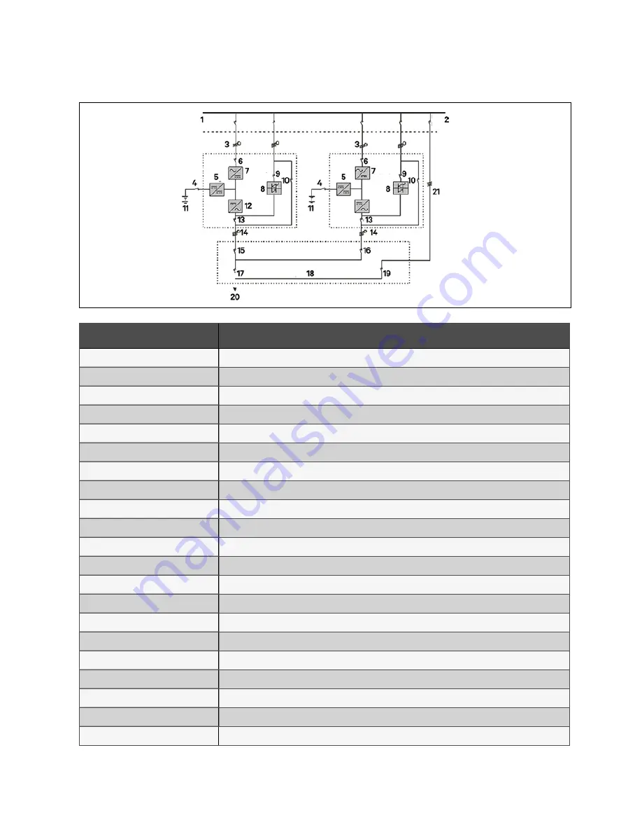
F igu re 8 .1 Sch em atic o f typical parallel system (with co m m o n in pu t, separate batteries an d o u tpu t)
N o.
D es crip tion
1
Input power supply
2
External bypass switch
3
Mains input L1, L2, L3, N
4
BCB
5
Charger
6
Q1
7
Rectified
8
Static switch
9
Q2
10
Q3
11
Battery 1
12
Inverter
13
Q5
14
L1, L2, L3, N
15
Q1EXT
16
Q2EXT
17
QUPS
18
Output distribution
19
QBYP
20
To load
21
External maintenance bypass
N O T E: Q 1, Q 2, an d Q 5 are o ptio n al wh ile Q 3 is stan dard.
8 Parallel System and LBS System
134
Vertiv™ Liebert® APM Plus User Manual
Содержание APM 0250kMK16FN02000
Страница 1: ...Vertiv Liebert APM Plus User Manual 50 250 kVA UPS...
Страница 8: ...vi This page intentionally left blank Vertiv Liebert APM Plus User Manual...
Страница 16: ...1 Important Safety Instructions 8 This page intentionally left blank Vertiv Liebert APM Plus User Manual...
Страница 30: ...2 Overview 22 This page intentionally left blank Vertiv Liebert APM Plus User Manual...
Страница 60: ...4 Electrical Installation 52 This page intentionally left blank Vertiv Liebert APM Plus User Manual...
Страница 73: ...Figure 5 11 Customize the display 5 Operator Control and Display Panel 65 Vertiv Liebert APM Plus User Manual...
Страница 97: ...5 Operator Control and Display Panel 89 Vertiv Liebert APM Plus User Manual...
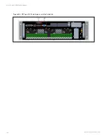
Страница 154: ...Figure 8 8 LBS port J4 on bypass control module 8 Parallel System and LBS System 146 Vertiv Liebert APM Plus User Manual...
Страница 182: ...11 Service and Maintenance 174 This page intentionally left blank Vertiv Liebert APM Plus User Manual...
Страница 188: ...12 Specifications 180 This page intentionally left blank Vertiv Liebert APM Plus User Manual...
Страница 191: ...Vertiv Liebert APM Plus User Manual...

