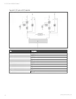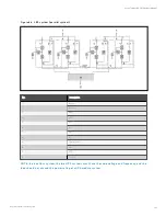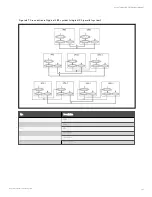
8.3.3 Procedures for Isolating One UPS module from Parallel System
IM P O R T A N T ! T h ese pro cedu res sh all o n ly be carried o u t by service perso n n el o f Vertiv o r u n der th eir
gu idan ce.
W A R N IN G ! A fter iso latin g o n e UP S m o du le, wh en th e parallel system is n o t o verlo ad, th en
pro ceed with steps belo w.
The following procedures apply when one UPS module must be isolated from the parallel system for repair due to serious
fault:
1.
Pressing the EPO button stops the operation of rectifier, inverter, static switch and battery, but this action will
not affect other UPSs in parallel system to power the load normally.
2.
Disconnect the external power mains switch, rectifier input switch Q1, external power bypass switch, bypass
input switch Q2, output switch Q5, BCB and single module external output switch.
W A R N IN G !
1. P o st a label at th e A C in pu t distribu tio n (gen erally far away fro m th e UP S) to alert th at th e
UP S m ain ten an ce is bein g o perated.
2. W ait 10 m in u tes fo r th e in tern al DC bu s capacitan ce disch argin g. T h en th e UP S is co m pletely
sh u t do wn .
8.3.4 Procedures for Inserting One Isolated UPS module in Parallel System
IM P O R T A N T ! T h ese pro cedu res sh all o n ly be carried o u t by service perso n n el o f Vertiv o r u n der th eir
gu idan ce.
The following procedures are used to reintegrate a UPS module that has been previously isolated from the parallel system:
1.
Confirm that the I/O cable, battery cable and parallel cable of the single module are correctly connected.
2.
Confirm that the maintenance bypass switch Q3 or the single module external maintenance switch is
disconnected. Close the output switch Q5, external output switch, external power bypass switch, bypass input
switch Q2, rectifier input switch Q1, and external power mains switch of each UPS in turn.
3.
When the single module starts, close the BCB and then manually turn on the inverter.
Wait a few seconds after starting the inverter of inserted UPS system, it connects with existing systems for parallel operation
automatically.
8 Parallel System and LBS System
140
Vertiv™ Liebert® APM Plus User Manual
Содержание APM 0250kMK16FN02000
Страница 1: ...Vertiv Liebert APM Plus User Manual 50 250 kVA UPS...
Страница 8: ...vi This page intentionally left blank Vertiv Liebert APM Plus User Manual...
Страница 16: ...1 Important Safety Instructions 8 This page intentionally left blank Vertiv Liebert APM Plus User Manual...
Страница 30: ...2 Overview 22 This page intentionally left blank Vertiv Liebert APM Plus User Manual...
Страница 60: ...4 Electrical Installation 52 This page intentionally left blank Vertiv Liebert APM Plus User Manual...
Страница 73: ...Figure 5 11 Customize the display 5 Operator Control and Display Panel 65 Vertiv Liebert APM Plus User Manual...
Страница 97: ...5 Operator Control and Display Panel 89 Vertiv Liebert APM Plus User Manual...
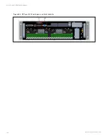
Страница 154: ...Figure 8 8 LBS port J4 on bypass control module 8 Parallel System and LBS System 146 Vertiv Liebert APM Plus User Manual...
Страница 182: ...11 Service and Maintenance 174 This page intentionally left blank Vertiv Liebert APM Plus User Manual...
Страница 188: ...12 Specifications 180 This page intentionally left blank Vertiv Liebert APM Plus User Manual...
Страница 191: ...Vertiv Liebert APM Plus User Manual...

