background image

Vertiv™ NetSure™ IPE Series -48 VDC Outdoor Rectifier Installation and User Manual 

Proprietary and Confidential © 2022 Vertiv Group Corp. 

39 

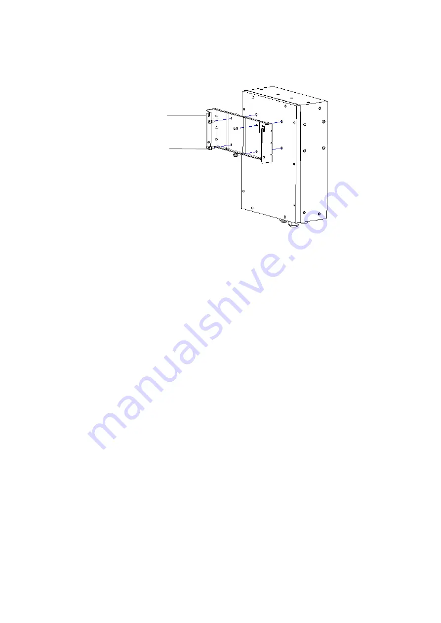
Figure 2.32  Install Rectifier Mounting Bracket to Li-ion Battery 


M6*16 P/N: 26020779 (4X)
Torque: 5 Nm

Mounting bracket
P/N: 63240DPV (1X)

Содержание 1R482000C2-1

Страница 1: ...NetSure IPE Series 48 VDC Outdoor Rectifier Installation and User Manual Specification Number 1R482000C2 1 1R482000C2 2 1R482000C2 3 Model Number R48 2000C2 BOM 31014424...

Страница 2: ...o be used in performing procedures not specifically described in this document The products covered by this instruction manual are manufactured and or sold by Vertiv This document is the property of V...

Страница 3: ...ecifications 17 1 6 3 Battery Storage Environment 18 1 6 4 Battery Maintenance 18 1 6 5 Precautions for Battery Use 18 2 Installation 19 2 1 General 19 2 2 Tools Required for Installation 19 2 3 Mount...

Страница 4: ...ction Procedure for PG Terminal 57 3 10 2 Customer Wiring Connection Procedure for Quick Connect Terminal 59 3 11 Battery Connections 67 3 11 1 General 67 3 11 2 Battery DB9 Pin Definition 67 3 11 3 R...

Страница 5: ...ce Operating System Version Requirements 78 7 3 2 Bluetooth APP 78 8 Troubleshooting and Repair 89 8 1 General 89 8 2 Alarm Conditions Identified by the Controller 89 8 3 Alarm Conditions Identified b...

Страница 6: ...inor or moderate injury if not avoided ANSI OSHA This admonition is not used for situations that pose a risk only to equipment data or service even if such use appears to be permitted in some of the a...

Страница 7: ...h circuits wiring used to provide power to the system before any AC electrical connections are made Follow local lockout tagout procedures to ensure upstream branch circuit breakers remain de energize...

Страница 8: ...fire They may explode Do not open or mutilate batteries ALWAYS FOLLOW THE BATTERY MANUFACTURER S RECOMMENDATIONS AND SAFETY INSTRUCTIONS Specific Precautions for the Batteries Described in this Docum...

Страница 9: ...or Electrical Safety in the Workplace Hazardous Voltage DANGER HAZARD OF ELECTRICAL SHOCK More than one disconnect may be required to de energize the system before servicing Handling Equipment Contain...

Страница 10: ...megohm resistor no external resistor is necessary Read and follow wrist strap manufacturer s instructions outlining use of a specific wrist strap 3 Do not touch traces or components on equipment conta...

Страница 11: ...ct Type with controller 1 Mounting Bracket Part A 2 For pole and wall mounting P N 63240ETT Mounting Bracket Part B 1 For pole mounting only P N 63240ETS Cross Recessed Countersunk Screw 2 For pole mo...

Страница 12: ...ector DB 15 Output Customer Side 1 Connector DB 9 I O Customer Side 1 NOTE The rectifier is equipped with plug in customer cable connectors Mating halves to these connectors are furnished as detailed...

Страница 13: ...es 20Ah or 50Ah battery 1 Connector DB 9 I O 1 Connector DC 2kW Output 2 1 3 Accessories 1 3 1 Mounting Kits Refer to Table 1 5 Table 1 5 Mounting Kits Part Number Description included with rectifier...

Страница 14: ...arked Table 1 7 Customer Wiring Selection EMEA Market P N Description Usage RPM629065 10 IP65 QC RECTIFIER TO BATTERY 2X10 0 8M Battery charge and discharge power cable RPM629065 11 IP65 QC MAIN R RS4...

Страница 15: ...d back reducing the voltage as shown in Figure 1 1 so as to limit the current and protect the rectifier The dotted line in Figure 1 1 represents the Fold Back 1 5 Rectifier Specifications The specific...

Страница 16: ...7 F This refers to a total of 120 hours in any given year but no more than 15 occurrences in that one year period Other power rating values are as follows refer to Figure 1 3 a At an ambient temperatu...

Страница 17: ...ltage does not exceed 1 millisecond 7 Filtering a Voice Band Noise Peak peak voltage is 200 mV at 0 MHZ to 20 MHZ and normal output voltage b Wide Band Noise Wideband noise voltage is 50 mV at 3 4 kHz...

Страница 18: ...0 231 17 330 25 2 319 510 03 500 44 0 981 94 39 28 060 50 4 509 991 15 984 13 0 993 96 18 37 550 75 6 740 1480 05 1474 08 0 996 96 47 52 07 100 9 793 2147 70 2143 99 0 998 96 10 83 691 240 0 0 673 16...

Страница 19: ...991 96 19 37 531 75 6 748 1481 92 1474 51 0 995 96 46 52 187 100 9 806 2150 63 2146 230 0 998 96 17 82 168 240 0 0 804 193 16 17 36 0 089 17 360 25 2 171 521 01 500 32 0 960 94 28 28 640 50 4 157 996...

Страница 20: ...3000 m 5 Surge Protection EN61000 4 5 up to level 4 Telcordia GR 1089 Core issue 7 2017 IEEE C62 41 1999 B3 AC Power Terminals Test Level Source Impedance Performance Criteria Line to Line Line to Gro...

Страница 21: ...surge Requirements on RS485 CAN bus Signals Are Minimum Peak Voltage volts Voltage Maximum Rise Minimum Decay Time s Minimum Peak Current per Conductor amperes Current Maximum Rise Minimum Decay Time...

Страница 22: ...Connector Circuit Dry Contact Implication Jumper Connection Dry Contact State when Alarm is Active DO1 Fuse Breaker Fail JP1 short pin 1 and 2 Open JP1 short pin 2 and 3 Closed DO2 SPD Alarm Fail JP2...

Страница 23: ...t Current Limiting The rectifier has a current limit function The current limit point is factory set at 41 7 A The current limit accuracy is 1 5 A when the output voltage is in the range from 42 VDC t...

Страница 24: ...ters 400 Height X 300 Width X 62 Depth b Inches 15 7 Height X 11 8 Width X 2 4 Depth Weight 9 kg Color Vertiv EG123 per RAL9003 Signal white or equivalent Indicators The following indicators are locat...

Страница 25: ...Group Corp 15 1 6 Battery 1 6 1 Battery Appearance There are two types of batteries 20AH Battery see Figure 1 7 and Figure 1 8 50AH Battery see Figure 1 9 and Figure 1 10 Figure 1 7 20AH Battery Side...

Страница 26: ...e IPE Series 48 VDC Outdoor Rectifier Installation and User Manual Proprietary and Confidential 2022 Vertiv Group Corp 16 Figure 1 9 50AH Battery Side View Figure 1 10 50AH Battery Bottom View RS485 C...

Страница 27: ...no less than 700 times When the ambient temperature is 40 the battery pack s 100 DOD cycle life should be no less than 600 times Size 400x300x130mm 400x300x240mm Work Temperature Range 40 55 40 55 Wor...

Страница 28: ...he battery pack become dirty wipe them with a dry cloth before use Otherwise the battery pack will have poor contact causing energy loss or failure to charge 1 6 5 Precautions for Battery Use 1 Batter...

Страница 29: ...for Installation Refer to Table 2 1 for a list of tools required for installation Table 2 1 Tools Required for Installation Tool Specification Tool Specification Combination wrench hatch club Wrench s...

Страница 30: ...ng Kit P N 02236200 for One 1 Rectifier and One 1 Battery Flag Installation This optional kit allows a battery and rectifier to be mounted to a pole or wall in a flag orientation See Figure 2 2 Figure...

Страница 31: ...igure 2 3 Figure 2 3 Optional Mounting Kit P N 02236201 for One 1 Rectifier and One 1 Battery Flat Installation Torx Head Screw M6 16 26020795 8X Connector 631200J1 1X Torx Head Screw M6 16 26020795 2...

Страница 32: ...r and mounting accessories and kits 2 Install the mounting bracket 63240ETT in the appropriate top position on the pole with the supplied pole mount band Securely tighten the pole mount band to the po...

Страница 33: ...ets to the Rear Panel of the Rectifier Flag Figure 2 6 Installing the Mounting Brackets to the Rear Panel of the Rectifier Flat Mounting bracket P N63240ETS M6 10 P N 26020778 2X Torque 5Nm M6 16 P N...

Страница 34: ...nfidential 2022 Vertiv Group Corp 24 Figure 2 7 Securing the Rectifier to the Pole at the Top Flag Figure 2 8 Securing the Rectifier to the Pole at the Top Flat Hook the hanger in the bracket slot M6...

Страница 35: ...Manual Proprietary and Confidential 2022 Vertiv Group Corp 25 Figure 2 9 Securing the Rectifier to the Pole at the Bottom Flag Figure 2 10 Securing the Rectifier to the Pole at the Bottom Flat Pole mo...

Страница 36: ...appropriately sized holes for the customer provided M10 wall anchors being used into the wall as shown in Figure 2 11 Install the M10 wall anchors into the holes Figure 2 12 3 Install the mounting br...

Страница 37: ...idential 2022 Vertiv Group Corp 27 Figure 2 13 Installing the Mounting Brackets to the Rectifier Flag Figure 2 14 Installing the Mounting Brackets to the Rectifier Flat M6 16 P N 26020779 4X Torque 5N...

Страница 38: ...or Rectifier Installation and User Manual Proprietary and Confidential 2022 Vertiv Group Corp 28 Figure 2 15 Installing the Rectifier to the Wall Flag Figure 2 16 Installing the Rectifier to the Wall...

Страница 39: ...tomer needs to supply four 4 wall anchors capable of supporting the weight of the rectifier and battery NOTE If the rectifier s front access panel is opened during installation ensure the access panel...

Страница 40: ...Series 48 VDC Outdoor Rectifier Installation and User Manual Proprietary and Confidential 2022 Vertiv Group Corp 30 Figure 2 17 Install Mounting Brackets to Pole Figure 2 18 Install Mounting Brackets...

Страница 41: ...Outdoor Rectifier Installation and User Manual Proprietary and Confidential 2022 Vertiv Group Corp 31 Figure 2 19 Install Mounting Brackets to Rectifier Figure 2 20 Install Li ion Battery to Pole M8...

Страница 42: ...tiv NetSure IPE Series 48 VDC Outdoor Rectifier Installation and User Manual Proprietary and Confidential 2022 Vertiv Group Corp 32 Figure 2 21 Install Rectifier to Pole M6 16 P N 26020795 2X Torque 5...

Страница 43: ...stomer provided M10 wall anchors being used into the wall as shown in Figure 2 22 Install the M10 wall anchors into the holes Figure 2 23 3 Install mounting bracket to wall Refer to Figure 2 24 4 Inst...

Страница 44: ...ual Proprietary and Confidential 2022 Vertiv Group Corp 34 Figure 2 24 Install Mounting Bracket to Wall Figure 2 25 Install Mounting Bracket to Li ion Battery M10 Torque 40 Nm Mounting bracket P N 633...

Страница 45: ...User Manual Proprietary and Confidential 2022 Vertiv Group Corp 35 Figure 2 26 Install Mounting Bracket to Rectifier Figure 2 27 Install Li ion Battery to Wall Mounting bracket P N 21243139 Small M6...

Страница 46: ...customer needs to supply four 4 wall anchors capable of supporting the weight of the rectifier and battery NOTE If the rectifier s front access panel is opened during installation ensure the access pa...

Страница 47: ...ifier Refer to Figure 2 33 7 Install Li ion battery to pole Refer to Figure 2 34 8 Install rectifier to Li ion battery Refer to Figure 2 35 9 Install bottom mounting screws to rectifier Tighten top an...

Страница 48: ...idential 2022 Vertiv Group Corp 38 Figure 2 30 Install Li ion Battery Optional Mounting Bracket if required Figure 2 31 Install Pole Mounting Bracket to Li ion Battery Mounting Bracket battery flat in...

Страница 49: ...Outdoor Rectifier Installation and User Manual Proprietary and Confidential 2022 Vertiv Group Corp 39 Figure 2 32 Install Rectifier Mounting Bracket to Li ion Battery M6 16 P N 26020779 4X Torque 5 Nm...

Страница 50: ...or Rectifier Installation and User Manual Proprietary and Confidential 2022 Vertiv Group Corp 40 Figure 2 33 Install Top Mounting Screws to the Rectifier M6 16 P N 26020795 2X Keep the distance betwee...

Страница 51: ...lation and User Manual Proprietary and Confidential 2022 Vertiv Group Corp 41 Figure 2 34 Install Li ion Battery to Pole Figure 2 35 Install Rectifier to Li Battery Screws hang into their slots along...

Страница 52: ...nfidential 2022 Vertiv Group Corp 42 Figure 2 36 Install Bottom Mounting Screws to Rectifier and Tighten Top and Bottom Rectifier Mounting Screws Figure 2 37 Install Rectifier and Li ion Battery Conne...

Страница 53: ...ure 2 40 4 Install Li ion battery optional mounting bracket if required Refer to Figure 2 41 5 Install wall mounting bracket to Li ion battery Refer to Figure 2 42 6 Installing rectifier mounting brac...

Страница 54: ...User Manual Proprietary and Confidential 2022 Vertiv Group Corp 44 Figure 2 40 Install Mounting Bracket to Wall Figure 2 41 Install Li ion Battery Optional Mounting Bracket if required M10 Torque 40 N...

Страница 55: ...onfidential 2022 Vertiv Group Corp 45 Figure 2 42 Install Wall Mounting Bracket to Li ion Battery Figure 2 43 Install Rectifier Mounting Bracket to Li ion Battery Mounting bracket Big P N 21243067 M8...

Страница 56: ...door Rectifier Installation and User Manual Proprietary and Confidential 2022 Vertiv Group Corp 46 Figure 2 44 Install Top Mounting Screws to Rectifier M6 16 P N 26020795 2X Keep the distance between...

Страница 57: ...tion and User Manual Proprietary and Confidential 2022 Vertiv Group Corp 47 Figure 2 45 Install Li ion Battery to Wall Figure 2 46 Install Rectifier to Li ion Battery M8 16 P N 26020780 2x Torque 12 N...

Страница 58: ...nfidential 2022 Vertiv Group Corp 48 Figure 2 47 Install Bottom Mounting Screws to Rectifier and Tighten Top and Bottom Rectifier Mounting Screws Figure 2 48 Install Rectifier and Li ion Battery Conne...

Страница 59: ...pull on the physical connector termination or joint Connectors are IP65 rated when not accommodating installation cord or cable tension or pull At installation use only approved outdoor rated devices...

Страница 60: ...ure the access panel is securely closed and the screws are torqued to 2 5 Nm 3 2 Wiring Considerations All wiring and branch circuit protection should follow the local national electrical building sta...

Страница 61: ...ly CAN Alarm interface Load output interface 1 Battery interface Load output interface 2 Load output interface 3 Power input interface CAN Alarm interface Load output interface 1 Battery interface Loa...

Страница 62: ...llation local codes and your specific site requirements 3 4 2 Positive Grounding As default the power system is not positive grounded Connect the grounding wire as shown in Figure 3 2 to ground positi...

Страница 63: ...mm AC Input L N 2 5 mm2 L 12 mm AC Input PE 2 5 mm2 stud M3 PE 10 mm2 L 25 4 mm screw M6 L 25 4 mm or NOTE Terminals to be customer supplied 3 5 2 Quick Connect Version Table 3 2 Quick Connect Versio...

Страница 64: ...gital Output DO Relay Functions The alarm relay contact configurations can be changed Refer to the following procedure Procedure 1 Refer to Opening Closing the Front Access Panel on page 75 and open t...

Страница 65: ...This is for PG Gland Wiring version only 8 Conductor Cable 24 AWG to 26 AWG leads 4 PR DO s Recommended Shielded Twisted Pair STP Cable 2 Conductor Cable Battery Rectifier RS 485 Communication 24 AWG...

Страница 66: ...Proprietary and Confidential 2022 Vertiv Group Corp 56 Figure 3 4 Strip insulation off the wires for RECTIFIER AC INPUT as required for PG gland version mm Figure 3 5 Strip insulation off the wires f...

Страница 67: ...5 6 LOAD1 PG29 Cable Gland 13 20 2KW DC Output1 and Output1 BAT PG29 Cable Gland 13 20 2KW BAT Input Output2 and Output2 LOAD2 PG21 Cable Gland 9 16 1KW DC Output3 and Output3 LOAD3 PG21 Cable Gland...

Страница 68: ...void sheath degrades 5 Tighten the screw of the terminal block as required 6 Tighten the caps of cable gland connectors as required Figure 3 8 Customer Wiring Connection Caps and Sealing pins OUT 1 OU...

Страница 69: ...ct Terminal Refer to the illustrations in the following procedures Refer also to Table 3 4 Table 3 4 Designation for Customer Wiring Connection Designation Connector Acceptable Cable Outer Diameter Ra...

Страница 70: ...rtiv NetSure IPE Series 48 VDC Outdoor Rectifier Installation and User Manual Proprietary and Confidential 2022 Vertiv Group Corp 60 Power Input Interface Figure 3 9 AC Power 3 Terminal Input Interfac...

Страница 71: ...lation and User Manual Proprietary and Confidential 2022 Vertiv Group Corp 61 Battery Load Output Interface 1 NOTE If the connector is not be used then the sealing pins and cap must not be removed Fig...

Страница 72: ...nd User Manual Proprietary and Confidential 2022 Vertiv Group Corp 62 Load Output Interface 2 Load Output Interface 3 NOTE If the connector is not be used then the sealing pins and cap must not be rem...

Страница 73: ...tiv NetSure IPE Series 48 VDC Outdoor Rectifier Installation and User Manual Proprietary and Confidential 2022 Vertiv Group Corp 63 CAN and Alarm Interface DB15 Wiring Instruction Figure 3 12 DB15 Wir...

Страница 74: ...al Output 1 Alarm output 3 Digital Output 2 Alarm output 4 Digital Output 2 Alarm output 5 Digital Output 3 Alarm output 6 RS485_2A The northbound interface to the NMS Network Management System 7 RS48...

Страница 75: ...Vertiv NetSure IPE Series 48 VDC Outdoor Rectifier Installation and User Manual Proprietary and Confidential 2022 Vertiv Group Corp 65 DB9 Wring Instruction Figure 3 14 DB9 Wiring...

Страница 76: ...S485_1A The southbound RS485 interface to the LIB 2 RS485_1A The southbound RS485 interface to the LIB 3 4 5 6 CAN Communicate with other rectifiers for parallel installation 7 CAN Communicate with ot...

Страница 77: ...are connected in parallel the battery protection is triggered for the unbalanced discharge current between the pre discharged batteries When connecting in parallel the following coefficients are requi...

Страница 78: ...re IPE Series 48 VDC Outdoor Rectifier Installation and User Manual Proprietary and Confidential 2022 Vertiv Group Corp 68 3 11 3 Rectifier and Battery Wire Diagram Figure 3 17 Rectifier and Battery W...

Страница 79: ...to Figure 3 18 for DIP switch location NOTE System with multi batteries is only applicable for EMEA region Please find your local sales agent for detail information 3 12 2 Power Switch The power rocke...

Страница 80: ...the unit NOTE You only need the Micro SIM card if you are using NB IoT 1R482000C2 1 only Procedure 1 Refer to Opening Closing the Front Access Panel on page 75 and open the rectifier enclosure front...

Страница 81: ...re to turn Bluetooth in the rectifier ON or OFF Procedure 1 Refer to Opening Closing the Front Access Panel on page 75 and open the rectifier enclosure front access panel 2 Refer to Figure 4 2 and set...

Страница 82: ...door Rectifier Installation and User Manual Proprietary and Confidential 2022 Vertiv Group Corp 72 4 3 Antenna Installation For R48 2000C2 1 Only See Figure 4 3 Figure 4 3 Antenna Installation Tighten...

Страница 83: ...osition apply AC input power to the rectifier by closing the external AC disconnect or protective device The rectifier starts automatically 3 Apply battery power to the system by placing the battery O...

Страница 84: ...nal Figure 6 1 Local Indicator Locations Table 6 1 Local Indicators Indicator Color Normal State Fault State Fault Cause Status Green On Off No operation power supply Observation Alarm Yellow Off On T...

Страница 85: ...ccess Panel Procedure 1 Rotate the access panel clockwise 180 around the hardware of the top left corner Refer to Figure 6 2 and Figure 6 3 Tighten the hardware circled in Figure 6 3 to secure the acc...

Страница 86: ...rtiv NetSure IPE Series 48 VDC Outdoor Rectifier Installation and User Manual Proprietary and Confidential 2022 Vertiv Group Corp 76 Figure 6 4 Close the Access Cover Tighten the screw as torqued 2 5...

Страница 87: ...dependent on interference sources at the installation site The controller acquires batteries and rectifiers information analyses and processes these to monitor and manage the healthy operation of powe...

Страница 88: ...id Version Android 4 4 and above Android Phone Screen size of 4 7 or larger Figure 7 3 APP Running on an IOS Device 7 3 2 Bluetooth APP General The controller provides a mobile wireless communication...

Страница 89: ...ntent may be different according to the configuration system mode and system status Bluetooth Login Screen Supported Application Language English There are two account types Read Only and Read Write R...

Страница 90: ...roup Corp 80 Figure 7 5 Privacy Policy Page Figure 7 6 Terms Conditions Page Bluetooth Connection Procedure 1 After logging into the controller via the App click Bluetooth Connection 2 A list of suppo...

Страница 91: ...een 1 The Homepage screen includes a Menu Navigation and a System Status Information area see Figure 7 8 2 From the Menu Navigation area you can navigate to the other screens as shown below 3 From the...

Страница 92: ...etting Swap Controller and About The Menu Navigation area appears in the Home screen Alarm screen Setting screen Swap Controller screen and About screen Home Icon When in other screens click on the Ho...

Страница 93: ...Alarm Level Phase A Voltage Low OA Phase A Voltage High OA Phase B Voltage Low OA Phase B Voltage High OA Phase C Voltage Low OA Phase C Voltage High OA AC Freq Low OA AC Freq High OA Mains Failure MA...

Страница 94: ...Response MA Alarm Block Level None MPPT Overwork Alarm None Setting Icon In the Menu Navigation area click on the Setting Icon to go to the Setting screen The settings are divided into Value Setting...

Страница 95: ...les the ECO Mode Alarm Block When the outgoing alarms are blocked the alarms shall not trigger relay outputs The active alarms are continued to be displayed in the mobile app and in the Web pages Sele...

Страница 96: ...gure 7 13 About Screen About Screen The About screen displays the Product Model Controller Revision Software Revision Serial Number and App Version System Status Information Rectifier Icon In the Home...

Страница 97: ...al 2022 Vertiv Group Corp 87 Figure 7 15 Rectifier Information Screen Battery Icon In the Homepage screen click on the Battery Icon to go to the Battery screen Figure 7 16 Battery Screen Battery Infor...

Страница 98: ...Vertiv NetSure IPE Series 48 VDC Outdoor Rectifier Installation and User Manual Proprietary and Confidential 2022 Vertiv Group Corp 88 Figure 7 17 Battery Information Screen...

Страница 99: ...C low voltage alarm setting Check why voltage is low Phase C Voltage High Voltage is above Phase C high voltage alarm setting Check why voltage is high AC Freq Low AC frequency is below low frequency...

Страница 100: ...k that it is not caused by open AC input circuit breaker The system load is higher than rectifier capacity causing the batteries to discharge install additional rectifiers Rect Overload Output overloa...

Страница 101: ...the rectifier should be replaced in its entirety No attempt should be made to troubleshoot or repair individual components inside the rectifier enclosure except fuse replacement 8 4 2 Rectifier Fuses...

Страница 102: ...o hook the fuse that need to be replaced by the tool slot then pull it straight out of the fuseholder please refer to picture 2 Insert new fuse into tool slot please refer to picture3 Note that the ne...

Страница 103: ...er Installation and User Manual Proprietary and Confidential 2022 Vertiv Group Corp Connect with Vertiv on Social Media https www facebook com vertivI https www instagram com vertiv https www linkedin...

Страница 104: ...r registered trademarks of their respective owners While every precaution has been taken to ensure accuracy and completeness here Vertiv Group Corp assumes no responsibility and disclaims all liabilit...

Отзывы: