EXS
76
User Manual 10H52260UM60 - Rev. 1 - 10/2017
1. These procedures result in mains voltage being applied to the UPS output terminals.
2. If any loads are connected to the UPS output terminals, check with the user that it is safe to apply power. If the load is not
ready to receive power, please disconnect the downstream load switch, and apply a warning label at the load connection point.
Use the following procedures to switch the UPS on when it is in the fully switched off state.
1. Confirm that all the external maintenance bypass switches are in the off position. Ensure that the internal
maintenance bypass switch Q3 is in the off position, and that the input cables and copper bars and the parallel
cables are connected securely.
Warning
To avoid generating spurious fault messages, whenever it is necessary to switch the maintenance bypass switch to the on or off
position, the operation must be completed within three seconds.
2. Close all the bypass input switches.
3. Close the UPS bypass input switch Q2, rectifier input switch Q1, output switch Q5 and all external output isolating
switches (if any) in that order.
At this point, the system is switched on.
4. Press the UPS power buttons one by one to start the respective inverters.
Operating Procedures in Maintenance Bypass Mode
Warning
If the UPS system consists of more then 2 UPS modules in parallel, and the load capacity exceeds the single module capacity,
do not use the internal maintenance bypass switch.
This operation will transfer the load from the UPS power supply protection state to direct connection with AC input
bypass state.
Caution: risk of interruption of power supply to load
Before performing this procedure, you should check the LED information first, and make sure the bypass is normal and
synchronized with the inverter. Failure to do so may result in a brief interruption in the power supply to the load.
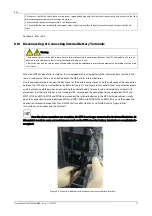
1. Remove the maintenance bypass switch baffle retaining screws, rotate the baffle upwards until it is locked in
position, and then fasten the retaining screws. Refer to Figure 5-13.
At this point, the system Interlock function has been activated and the UPS will transfer to internal bypass mode;
you should confirm that the UPS has been transferred to internal bypass mode.
2. After confirming, close the maintenance bypass switch Q3.
3. Disconnect the output switch Q5. At this point the load is powered by the maintenance bypass.
Caution
When the UPS is in maintenance bypass mode, the load is not protected against abnormalities in the mains power supply.
4. Unplugging the REPO terminal deactivates the rectifier, inverter, static switch and battery, but does not affect the
maintenance bypass power supply to the load.
Note
In maintenance mode, the load is fed directly by the mains power instead, of the pure AC power from the inverter.
5. If the UPS is equipped with an external battery, set the corresponding external battery switch to the off position
until all the UPS modules have been disconnected from the batteries.

