background image

36

20306757

CSDV Series Direct Vent Gas Stove

NOTE REGARDING VENTED PRODUCTS

This product must be installed by a licensed plumber or gas fitter 

when installed within the Commonwealth of Massachusetts.
Any residence with a direct vent product must have a carbon 

monoxide (CO) detector installed in the residence.

Installation of the fireplace or vented gas log in the State of 

Massachusetts requires the damper to be permanently removed 

or welded in the fully open position.
In addition, a naturally vented gas log may not be installed in a 

bedroom or bathroom in the State of Massachusetts.
Flex line installation must not exceed 36 inches and must have a 

T shutoff valve. 

NOTE REGARDING VENT FREE PRODUCTS

This product must be installed by a licensed plumber or gas fitter 

when installed within the Commonwealth of Massachusetts.
In addition, vent free products may not be installed in a 

bedroom or bathroom regardless of size or type in the State of 

Massachusetts.
Flex line installation must not exceed 36 inches and must have a 

T shutoff valve.

CARBON MONOXIDE DETECTOR REQUIREMENTS

(2) Revise 10.8.3 by adding the following additional 

requirements:

(a)  For all side wall horizontally vented gas fueled equipment 

installed in every dwelling, building or structure used in whole 

or in part for residential purposes, including those owned 

or operated by the Commonwealth and where the side wall 

exhaust vent termination is less than seven (7) feet above 

finished grade in the area of the venting, including but not limited 

to decks and porches, the following requirements shall be 

satisfied:

1. 

Installation of carbon monoxide detectors. 

At the time 

of installation of the side wall horizontal vented gas fueled 

equipment, the installing plumber or gas fitter shall observe 

that a hard wired carbon monoxide detector with an alarm and 

battery back-up is installed on the floor level where the gas 

equipment is to be installed. In addition, the installing plumber 

or gas fitter shall observe that a battery operated or hard wired 

carbon monoxide detector with an alarm is installed on each 

additional level of the dwelling, building or structure served by 

the side wall horizontal vented gas fueled equipment. It shall be 

the responsibility of the property owner to secure the services of 

qualified licensed professionals for the installation of hard wired 

carbon monoxide detectors


a.  In the event that the side wall horizontally vented gas 

fueled equipment is installed in a crawl space or an attic, the 

hard wired carbon monoxide detector with alarm and battery 

back-up may be installed on the next adjacent floor level.


b.  In the event that the requirements of this subdivision 

can not be met at the time of completion of installation, the 

owner shall have a period of thirty (30) days to comply with the 

above requirements; provided, however, that during said thirty 

(30) day period, a battery operated carbon monoxide detector 

with an alarm shall be installed.

MASSACHUSETTS RESIDENTS ONLY

2. 

Approved Carbon Monoxide Detectors.


Each carbon 

monoxide detector as required in accordance with the above 

provisions shall comply with NFPA 720 and be ANSI/UL 2034 

listed and IAS certified.

3. 

Signage.

 A metal or plastic identification plate shall 

be permanently mounted to the exterior of the building at a 

minimum height of eight (8) feet above grade directly in line with 

the exhaust vent terminal for the horizontally vented gas fueled 

heating appliance or equipment. The sign shall read, in print size 

no less than one-half (1/2) inch in size, “GAS VENT DIRECTLY 

BELOW. KEEP CLEAR OF ALL OBSTRUCTIONS.”

4. 

Inspection.

 The state or local gas inspector of the side 

wall horizontally vented gas fueled equipment shall not approve 

the installation unless, upon inspection, the inspector observes 

carbon monoxide detectors and signage installed in accordance 

with the provisions of 248 CMR 5.08(2)(a)1 through 4.
(b) 

Exemptions:

 The following equipment is exempt from 248 

CMR 5.08(2)(a)1 through 4:

1. The equipment listed in Chapter 10 entitled "Equipment Not 

Required To Be Vented" in the most current edition of NFPA 54 

as adopted by the Board; and

2. Product Approved side wall horizontally vented gas fueled 

equipment installed in a room or structure separate from the 

dwelling, building or structure used in whole or in part for 

residential purposes.
(c)  

Manufacturer requirements — Gas Equipment Venting 

System Provided.


When the manufacturer of Product 

Approved side wall horizontally vented gas equipment provides 

a venting system design or venting system components with 

the equipment, the instructions provided by the manufacturer 

for installation of the equipment and the venting system shall 

include:

1. Detailed instructions for the installation of the venting 

system design or the venting system components; and

2. A complete parts list for the venting system design or 

venting system.
(d) 

Manufacturer requirements — Gas Equipment Venting 

System Not Provided. 

When the manufacturer of a Product 

Approved side wall horizontally vented gas fueled equipment 

does not provide the parts for venting the flue gases, but 

identifies “special venting systems,” the following requirements 

shall be satisfied by the manufacturer:

1. The referenced "special venting system" instructions 

shall be included with the appliance or equipment installation 

instructions; and

2. The “special venting systems” shall be Product Approved 

by the Board, and the instructions for that system shall include a 

parts list and detailed installation instructions.
(e)  A copy of all installation instructions for all Product Approved 

side wall horizontally vented gas fueled equipment, all venting 

instructions, all parts lists for venting instructions, and/or all 

venting design

Please read and follow these special requirements

Содержание CSDV30NVEMBCSB

Страница 1: ...Immediately call your gas supplier from a neighbor s phone Follow the gas supplier s instructions If you cannot reach your gas supplier call the fire department Installation and service must be perfor...

Страница 2: ...tems Needed 22 Check Gas Pressure 23 CONGRATULATIONS You have purchased a state of the art gas appliance featuring the Lex Fire Burn System available exclusively on Vermont Castings Group The Lex Fire...

Страница 3: ...alled by a qualified service person The glass door must be properly seated and sealed If this unit is not properly installed by a qualified service person with glass door properly seated and sealed co...

Страница 4: ...replacement of the unit 19 Do not operate stove if any log is broken 20 Do not use a blower insert heat exchanger insert or other accessory not approved for use with this stove 21 Do not operate the...

Страница 5: ...DV Cast Iron Stove Controls ON OF F FP2724 CSDV controls Pilot Optional Remote Receiver Door Hi Lo Knob On Off Switch Optional Blower Ignitor Box Located Under Right Front Leg HIGH ELEVATIONS Input ra...

Страница 6: ...6 20306757 CSDV Series Direct Vent Gas Stove STOVE DIMENSIONS Figure 2 Stove Dimensions 586056 CSDV dims 261 2 673 mm 21 533 mm 281 2 724 mm...

Страница 7: ...ts Locate the stove where it can be accessed by a gas supply line Locate the stove in a large and open room that is centrally located in the house This will optimize heat circulation and comfort The f...

Страница 8: ...ll be installed on a metal wood or noncombustible material panel extending full width and depth of the appliance A E Minimum D Minimum to Either Side Wall ST1128 sidewall clearance Ceiling Mantel Side...

Страница 9: ...F A C B ST1132 alcove clearances Figure 5 Alcove Clearances NOTE Maintain minimum side and back clearances when placing stove in alcove ALCOVE CLEARANCES ALCOVE MINIMUM DIMENSIONS Height from Hearth W...

Страница 10: ...from inside of unit 7 Lift unit off pallet Lift unit up high enough to clear upright supports unit is sitting on NOTE You will need at least two 2 strong people to lift unit off of pallet UNPACKING ON...

Страница 11: ...outside The venting system must NEVER be attached to a chimney serving a separate solid fuel burning appliance Each gas appliance must use a separate vent system Do not use common vent systems WARNIN...

Страница 12: ...s Minimum clearance between vent pipes and combustible materials such as insulation is 1 WARNING Never run the vent pipe level or downward This may cause excessive temperatures which could cause a fir...

Страница 13: ...for appliances 100 000 BTU h 30kW 6 15cm for appliances 10 000 BTU h 3kW 9 23cm for appliances 10 000 BTU h 3kW and 50 000 BTU h 15kW 12 30cm for appliances 50 000 BTU h 15kW C Clearance to permanentl...

Страница 14: ...stible Noncombustible 12 305 mm M Balcony with perpendicular side wall M 12 305 mm P 6 152 mm M F Alcove Applications C D C E V V Combustible Noncombustible E Min 2 51 mm for non vinyl sidewalls Min 1...

Страница 15: ...male end of adjacent pipes and fittings Push the pipe sections together and twist one section clockwise approximately one quarter turn until the sections are fully locked Figure 14 FP1953 rigid pipe...

Страница 16: ...vent pipe before con necting the horizontal run to the vent cap Figure 18 6 Carefully move the stove with vent assembly attached toward the wall and insert the vent pipe into the hori zontal terminat...

Страница 17: ...tention to these installation instructions for required clearances air space to combustibles when passing through ceilings walls roofs enclosures attic rafters etc Do not pack air spaces with insulati...

Страница 18: ...ole must be measured on the horizontal Actual length may be larger depending on the pitch of the roof There must be a 1 minimum clearance from the vent pipe to combustible materials Frame the opening...

Страница 19: ...al ceiling installations can be very tricky 1 Remove shingles or other roof covering as necessary to cut the rectangular hole for the support box Mark the outline of the cathedral ceiling support box...

Страница 20: ...gure 27 Vertical Rigid Venting Configuration using Three 3 90 Elbows with Two 2 Horizontal Runs H V V1 ST1146 vert vent 2 elbows NOTE Install restrictor into 4 collar of stove or first vent section as...

Страница 21: ...Number Description 902B 65 8 x 48 Pipe 903B 65 8 x 36 Pipe 904B 65 8 x 24 Pipe 906B 65 8 x 12 Pipe 907b 65 8 x 9 Pipe 908B 65 8 x 6 Pipe 911B 65 8 Adjustable 11 145 8 Pipe 940 Wall Thimble 941 Cathed...

Страница 22: ...regulator The external regulator will reduce incoming gas pressure You must reduce incoming gas pressure to between 11 and 13 inches of water If you do not reduce incoming gas pressure burner system r...

Страница 23: ...t you install a sediment trap drip leg in supply line as shown in Figure 31 Locate sediment trap drip leg where it is within reach for cleaning Install in piping system between fuel supply and burner...

Страница 24: ...ational Electrical Code ANSI NFPA 70 latest edition and Canadian Electrical Code CSA C22 1 CAUTION Label all wires before disconnecting when servicing controls Wiring errors can cause improper and dan...

Страница 25: ...ins against left side of firebox 5 Place right base log 3 on the two pins against right side of firebox 6 Place top left log 4 on left base log Line up the notch in the bottom of the top log with the...

Страница 26: ...REN TO TOUCH GLASS A barrier designed to reduce the risk of burns from the hot viewing glass is provided with this appliance and shall be installed for the protection of children and other at risk ind...

Страница 27: ...neighbor s phone Follow the gas supplier s instructions If you cannot reach your gas supplier call the fire department C Use only your hand to push in or turn the gas control knob Never use tools If t...

Страница 28: ...urner connections Field made joints gas shutoff valve Pilot Factory made joints Each joint or connection All joints on valve and control body 1 Depress and turn knob counterclockwise to pilot position...

Страница 29: ...on is in the ON position to light the main burner LIGHTING THE BURNER Depress and turn the knob counterclockwise to the ON position It will take less than four 4 seconds for the burner to ignite PILOT...

Страница 30: ...high altitude as follows To increase air mixture pull down the adjustment rod located beneath the stove This opens the shutter more and will stop sooting Figure 37 To decrease air mixture push up the...

Страница 31: ...n the door Do not use abrasive cleaners They will damage the glass surface PILOT AND BURNER FLAMES Visually check pilot and burner flames periodically Refer to Figure 42 for typical pilot flame Refer...

Страница 32: ...s pane with tadpole gasket Make sure you have 1 4 overlap on each side 7 Place new glass in frame 8 Slide glass frame back down onto stove and fasten two clamps Figure 41 9 Insert front into the top o...

Страница 33: ...Adjust and retighten Pilot will not stay lit 1 Defective thermocouple Loose thermocouple 2 Air in gas line 3 No gas 1 Check for proper connection of thermocouple to rear of valve 2 Bleed line Contact...

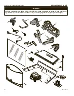
Страница 34: ...9 20 21 22 17 3 4 13 12 16 5 11 2 15 1 14 6 10 8 7 9 586056 CSDV30 parts 26 WARNING Failure to position the parts in accordance with these diagrams or failure to use only parts specifically approved w...

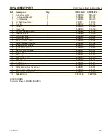
Страница 35: ...Knob 1 45D0237 45D0237 12 Knob Extension Hi Lo 1 43D0095 43D0095 13 Knob Extension ON OFF 1 43D0094 43D0094 14 Ignitor Battery Module 1 45D0077 45D0077 15 Ignitor Wire Harness 1 45D0500 45D0500 16 ON...

Страница 36: ...ys to comply with the above requirements provided however that during said thirty 30 day period a battery operated carbon monoxide detector with an alarm shall be installed MASSACHUSETTS RESIDENTS ONL...

Страница 37: ...tion damage damage from unauthorized service incidental or consequential damage or negative pressure caused by mechanical systems such as furnaces fans clothes dryers etc TERMS This warranty shall be...

Страница 38: ......

Страница 39: ......

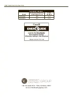
Страница 40: ...rchez dans la brochure les caract ristique de rendement nerg tique de foyer au gaz nerguide Selon CSA P 4 1 09 EFFICIENCY RATINGS Model EnerGuide Ratings Fire place Efficiency D O E AFUE CSDV30NV 65 4...

Отзывы: