background image

VSW40 Wood Stove

10

20300060

INSTALLATION

FLOOR PROTECTOR
Installation on a Concrete Floor

An appliance mounted on a concrete floor does not require 
floor protection.
Carpeting  and  any  other  combustible  material  shall  not 
cover the floor protector.
If a combustible surface is applied to the concrete floor, 
a  clearance  must  be  maintained  equivalent  to  the  area 
reserved for the floor protector. 

 Figure 4

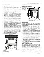
Installation on a Combustible Floor

If the appliance is to be installed on a combustible floor 
or a combustible floor covering, it must be installed on a 
non-combustible floor protector. The pad must be installed 
beneath the appliance extending 18" (457 mm) in Canada, 
16" (406 mm) in the U.S. on any side equipped with a door, 
and 8" (203 mm) on all other sides.  In the U.S. the pad 
must  cover  any  horizontal  chimney  connector  runs  and 
extend 2" (51 mm) beyond each side.

2” (51 mm)

2” (51 mm)

8”

(203 mm)

8”

(203 mm)

* 18” (457 mm)
** 16” (406 mm)

8”

(203 mm)

ST1059
SSW20 floor protection

* Canada 

** US

ST1059

Figure 4 - 
Installation on a Combustible Floor

ChIMNEY

Refer to chimney and chimney connector manufacturer’s 
instructions.

Contact your local building authority for approved methods 
of installation
1.  This appliance requires a masonry or pre-manufactured 

chimney listed to ULCS629 (Canada) and UL 103 HT 
(USA) sized correctly.

2.  If a masonry chimney is used it is advisable to have your 

chimney  inspected  for  cracks  and  check  the  general 
condition  before  you  install  your  unit.    Re-lining  may 
be required to reduce flue diameter to the appropriate 
functional size.

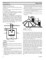
3.  The chimney should extend at least 3' (914 mm) above 

the highest point where it passes through the roof, and 
at least 2' (610 mm) higher than any portion of a building 
within 10' (3 m). 

Figure 5

4.  The chimney connector shall not pass through an attic, 

roof space, closet, concealed space, floor, ceiling, wall 
or any partition of combustible construction.

5.  The minimum overall height of your chimney should be 

15' (5 m) from the floor.

6.  Do  not  use  makeshift  compromises  during 

installation.

0 to 10’

2’ Min.

3’ Min.

0 to 10’

2’ Min.

3’ Min.

ST1012

2 3 10 rule

Reference Point

ST1012

Figure 5 - 
The 2'-3'-10' Chimney Rule

At  the  very  least,  inspect  the  chimney  connector  and 
chimney at least once every two months during the heating 
season to determine if a buildup of creosote or soot has 
occurred. If a significant layer of creosote has accumulated 
(1/8" (3 mm) or more], or if soot has accumulated, either 
should be removed to reduce the risk of a chimney fire. 
Failure to keep the chimney and connector system clean 
can result in a serious chimney fire.
The conditions for a chimney fire develop as follows: When 
wood is burned slowly, it produces tar and other organic 
vapors  which  combine  with  expelled  moisture  to  form 
creosote. The creosote vapors condense in the relatively 
cool  chimney  flue  of  a    slow  burning  fire. As  a  result 
creosote residue accumulates on the flue lining. Creosote 
is a flammable and, when ignited, make an extremely hot 
fire within the flue system which can damage the chimney 
and overheat adjacent combustible material.
To reduce the amount of creosote that may form, remember 
to provide adequate air for combustion and to strive for 
small, intense fires rather than large smoldering ones.
You can never be too safe. Contact your local fire authority 
for information on what to do in the event of a chimney 
fire, and have a clearly understood plan on how to handle 
one.

Содержание Challenger VSW40

Страница 1: ...ly installed a house fire may result To reduce the risk of fire follow the installation instructions Failure to follow instructions may result in property damage bodily injury or even death Contact lo...

Страница 2: ...NSTALLER Please leave these instructions with the appliance OWNER Please retain these instructions for future reference WARNING Proposition 65 Warning Fuels used in gas woodburning or oil fired applia...

Страница 3: ...n individual use depending on how the stove is operated type and moisture content of fuel and other factors Maximum burn times are achieved under different operating conditions than are maximum heat o...

Страница 4: ...icipal or provincial fire authority for information on how to handle a chimney fire Have a clearly understood plan to handle a chimney fire In the event of a chimney fire turn air control to closed po...

Страница 5: ...recommended wood load is level with the top of the firebricks Overloading may prevent sufficient air entering the heater to properly fuel the fire Important For optimum heater performance at low burn...

Страница 6: ...th 45 or 90 degree bends A bend requires the pipe to be removed for cleaning The stove baffle must be removed when cleaning the chimney see page 15 Chimney sweepings will build up on top of baffle cau...

Страница 7: ...fy maintenance If the stovepipe must elbow to enter a chimney locate the elbow about midway between the stovetop and the chimney thimble This configuration lets the smoke speed up before it must turn...

Страница 8: ...pe Installation Full Vertical A B C D E F G H I Single Wall Pipe 15 10 26 15 8 20 50 18 8 Flat top model 381 mm 254 mm 660 mm 381 mm 203 mm 508 mm 1270 mm 457 mm 203 mm Double Wall Pipe 13 8 23 12 Fla...

Страница 9: ...ng 1 25 mm or more of insulation and maintaining a minimum 2 inch air space between the outer wall of the chimney and combustibles ST1009 wall pass thru Chimney Connector 12 305 mm 12 305 mm ST1009 Fi...

Страница 10: ...oint where it passes through the roof and at least 2 610 mm higher than any portion of a building within 10 3 m Figure 5 4 The chimney connector shall not pass through an attic roof space closet conce...

Страница 11: ...can generate a chimney fire All of the installation characteristics that adversely affect chimney draft also promote creosote condensation Consequently you can minimize creosote accumulation with an...

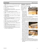
Страница 12: ...r control 10 08 Low Burn High Burn Figure 6 Air Control Layout ST1013 MAINTENANCE Removing firebrick To remove firebrick liftup from bottom and rotate o u t w a r d Figure 7 ST1018 remove firebrick Fi...

Страница 13: ...e c cast baffle is slid back against the steel non removable baffle Replace the rear bricks 1 Ensure appliance is not in operation and is thoroughly cooled 2 Remove door and place on a protected flat...

Страница 14: ...UNIT FREE OF CREOSOTE 1 Burn with air control open for several minutes at numerous intervals throughout the day during the heating season being careful not to over fire unit This removes the slight fi...

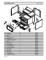
Страница 15: ...6 Handle Assy Ash Pan Door 1 63D0313 7 Ash Pan Door Cast Iron 1 63D0188 8 Fettle 1 63D3002 9 Airwash Cast Iron 1 63D3001 10 Shroud Left 1 63D3117 11 Tube Secondary Top 1 63D3006 12 Tube Air Bottom 4 6...

Страница 16: ...ient space in the firebox Adjust the air control setting to desired setting Page 12 i Note The lower the air control setting the longer the burn time of your firewood 2 What type of wood is best to us...

Страница 17: ...r or not there is sufficient air in your home for your stove curtail from using those appliances known to consume the air where possible or open a window or door to allow air to enter the home b Envir...

Страница 18: ...VSW40 Wood Stove 18 20300060...

Страница 19: ...e Warranty will also be void if the appliance is not operated and maintained according to the operating instructions supplied with the appliance and does not extend to 1 firebox burner assembly damage...

Страница 20: ...VSW40 Wood Stove 20 20300060 MHSC 149 Cleveland Drive Paris Kentucky 40361 www mhsc com...

Отзывы: