Control elements and connections
Front Panel/User Interface
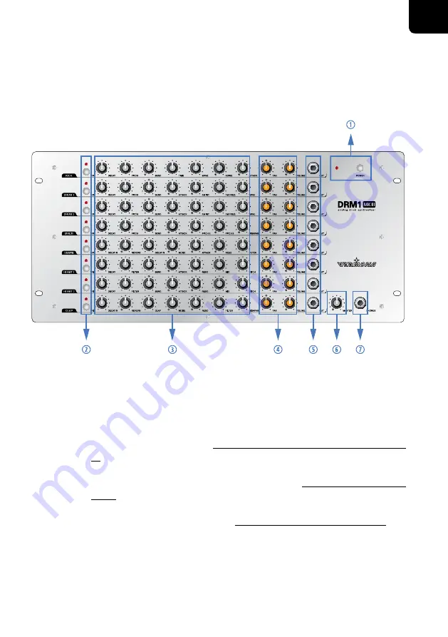
Figure 1: User Interface of the DRM1 MKIII
①
POWER
- power switch with LED
②
TRIG
button with LED - triggers sound in instrument channel
③
sound shaping parameters (see "The DRM1 MKIII’s instrument channels" on page
10)
④
PAN
and
VOLUME
- channel volume and panning (see "The Sound Generation" on
⑤
OUT
- individual outputs/inserts (see "Individual Outputs/Inserts" on page 20)
⑥
MASTER
- overall volume
⑦
PHONES
- headphones output
7
User Guide DRM1 MKIII
EN
Содержание DRM1 MKIII
Страница 1: ...Bedienungsanleitung User Guide DRM1 MKIII...


