background image

7.0

Repairs and Replacements

7.1

Safety Warning - Disconnection from Power Supply

Immediately switch the product off in the event of unforeseen
circumstances (e.g. large amount of smoke). Allow the product to return
to room temperature before inspection.

Always ensure that the product is disconnected from the electrical supply
before repair work is carried out.

Caution

: Double pole/neutral fusing may be used in this product.

7.2

Safety Warning - Refractory Fibre Insulation

Insulation made from High Temperature Insulation Wool

Refractory Ceramic Fibre, better known as (Alumina silicate
wool - ASW).

This product contains

alumino silicate wool

products in its thermal insulation. These

materials may be in the form of blanket or felt, formed board or shapes, slab or loose
fill wool.

Typical use does not result in any significant level of airborne dust from these materials,
but much higher levels may be encountered during maintenance or repair.

Whilst there is no evidence of any long term health hazards, it is strongly recommended
that safety precautions are taken whenever the materials are handled.

Exposure to fibre dust may cause respiratory disease.

When handling the material, always use approved respiratory protection
equipment (RPE-eg. FFP3), eye protection, gloves and long sleeved clothing.

Avoid breaking up waste material. Dispose of waste in sealed containers.

After handling, rinse exposed skin with water before washing gently with
soap (not detergent). Wash work clothing separately.

Before commencing any major repairs it is recommended to make reference to the
European Association representing the High Temperature Insulation Wool industry
(www.ecfia.eu).

Further information can be provided on request. Alternatively, Carbolite Gero Service
can quote for any repairs to be carried out either on site or at the Carbolite Gero
factory.

7.3

Temperature Controller Replacement

Refer to the controller instructions for more information on how to replace the
temperature controller.

29

7.0   Repairs and Replacements

Содержание CARBOLITE GERO MTF 12/25 Series

Страница 1: ...Installation Operation and Maintenance Instructions 1200 C Small Tube Furnace MTF Model 250 400mm 2416 Controller MTF 12 25 250 400 2416 Controller MEN MTF1225 003_2416 10 01 2019 ...

Страница 2: ...nnections 8 3 0 2416 Controller 10 3 1 Description 10 3 2 Operation 12 3 3 Programming 14 3 3 1 Programming Tips 14 3 3 2 Multi program model 2416P8 15 3 3 3 Holdback 15 3 3 4 Program Cycling 15 3 3 5 Running a Program 15 3 3 6 Program example 16 3 4 Controller Options 17 3 4 1 Digital Communications RS232 17 3 4 2 Digital Communications RS485 17 3 4 3 Comms Address 17 3 4 4 Alarm Option 17 3 5 Te...

Страница 3: ... 6 5 Recommended Spare Parts and Spare Parts Kit 28 7 0 Repairs and Replacements 29 7 1 Safety Warning Disconnection from Power Supply 29 7 2 Safety Warning Refractory Fibre Insulation 29 7 3 Temperature Controller Replacement 29 7 4 Solid State Relay Replacement 30 7 5 Thermocouple Replacement 30 7 6 Fuse Replacement 30 7 7 Element Replacement 32 8 0 Fault Analysis 33 A Furnace Does Not Heat Up 3...

Страница 4: ...d to the elements Heat switch the switch disconnects power to the heating elements unless this switch is OFF there is a danger of electric shock when inserting objects into the product 1 2 General Warnings DANGER Electric shock Read any warning printed next to this symbol WARNING Risk of fatal injury DANGER Hot surface Read any warning printed next to this symbol WARNING All surfaces of a product ...

Страница 5: ...Caution Double Pole Neutral Fusing 5 1 0 Symbols and Warnings ...

Страница 6: ...of heat and on a non flammable surface that is resistant to accidental spillage or hot materials The surface on which the equipment is mounted should be stable and not subject to movement or vibrations The height of the mounting surface is important to avoid operator strain when loading and unloading samples Unless otherwise stated elsewhere in this manual ensure that there is at least 150 mm of f...

Страница 7: ...rk tube or any accessories fit these into position Under no circumstances should any objects be placed on top of the product Always ensure that any vents on the top of the product are clear of any obstruction Always ensure all cooling vents and cooling fans if fitted are clear of any obstruction 2 3 Tube Fittings For optimum temperature uniformity insulating plugs should be placed in the tube ends...

Страница 8: ... to Neutral reversible non polarised or Live to Live Check the product rating label before connection The supply voltage should agree with the voltage on the label and the supply capacity should be sufficient for the current on the label The supply should be fused at the next size equal to or higher than the current on the label A table of the most common fuse ratings is also given towards the bac...

Страница 9: ...hen connecting the product to an isolating switch ensure that both conductors single phase or on all live conductors three phase and should be within reach of the operator The supply MUST incorporate an earth ground Supply Terminal Label Cable Colour Supply Types Live Neutral Reversible or Live Live 1 phase L Brown to live to either power conductor For USA 200 240V connect L1 N Blue to neutral to ...

Страница 10: ...ture controller where on setting the required tem perature the controller immediately attempts to reach and maintain it Fig 1 indic ates the type of temperature response when used in this way l By using one program segment the control can be extended to include ramp to set point Fig 2 shows the effect l Alternatively the 2416 Controller may be used as an 8 segment programmer with each segment bein...

Страница 11: ...ntrol Fig 2 Control with Ramp to Setpoint Seg 1 Ramp Sep 2 End Dwell Fig 3 A Program Key T1 Temperature T2 Time SP Setpoint AT Actual Temperature WSP Working Setpoint R Ramp D Dwell S Step E End 11 3 0 2416 Controller ...

Страница 12: ...nace or oven circuit this must be in an ON position 2416CG Operation When switched on the controller lights up goes through a short test routine and then displays the measured temperature and setpoint Depending on its state when it was last switched off it may start to control to the current setpoint of program The output light glows or flashes to indicate that the control is occurring The buttons...

Страница 13: ... displays the temperature units further presses reveal the parameters in the current list Some parameters are display only others may be altered by the operator Page Scroll Press together to cause an immediate return to the Home List Run Hold Indicate the current mode Run Hold or Reset Reset both lights off Run flashes at the end of a program Hold flashes during holdback when the program is paused...

Страница 14: ...ss all program segments are used Segments after End are ignored Segment Type Parameter Function RmP r TGt rATE The target setpoint for this segment The ramp rate rate of temperature change in minute RmP t TGt dur The target setpoint for this segment The duration of the segment The controller calculates the rate of temperature rise necessary to achieve this duration Dwel dur The time in minutes to ...

Страница 15: ...pplies to heating only Hi Holdback applies to cooling only Off Holdback is off Set Hb V to the value in C beyond which holdback is to operate Type BAnd and a value of 10 C is often a suitable combination if holdback is required In this case if the actual temperature deviates outside 10 C from the working setpoint the holdback lamp of the front of the controller flashes and the program is held up u...

Страница 16: ...scroll until tYPE is displayed and use the arrow key to select dwEl 9 Press scroll until dur is displayed and use the arrow key to select 60 0 10 Press scroll until SEG n is displayed and use the arrow key to select 3 11 Press scroll until tYPE is displayed and use the arrow key to select rmP t 12 Press scroll until tGt is displayed and use the arrow key to select 400 13 Press scroll until dur is ...

Страница 17: ...S232 Cable product to PC Computer end of cable 9 pin 25 pin male Rx 2 3 _________________ 3 2 Tx Tx 3 2 _________________ 2 3 Rx Com 7 5 _________________ 5 7 Com 7 8 4 5 Link together 1 4 6 6 8 20 Link together 3 4 2 Digital Communications RS485 If an RS485 option is supplied the furnace is fitted with two D sockets Connection between products is by straight cable as follows Product end of cable ...

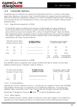
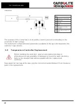
Страница 18: ...ent configuration and parameters available to the operator depend on the customer requirements 3 5 Temperature Controller Replacement Before handling the controller wear an anti static wrist strap or otherwise avoid any possibility of damage to the unit by static electricity Refer to the detailed instructions supplied with the replacement controller Ease apart the two lugs at the side grip the ins...

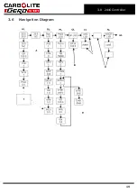
Страница 19: ...3 6 Navigation Diagram 19 3 0 2416 Controller ...

Страница 20: ...strument switch which cuts off power to the controller and other parts of the control circuit To operate the controller power must be supplied to the product and the instrument switch must be on If a time switch is included in the product circuit this must be in the ON position When an over temperature condition occurs the controller cuts the power to a contactor which in turn cuts power to the he...

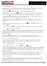
Страница 21: ...perature set at 15 C above the furnace or oven maximum working temperature Press scroll twice view the present temperature as measured by the over temperature controller Press it twice the first press shows the temperature units C 4 2 4 Over Temperature Alarm If an over temperature condition occurs the OP2 indicator flashes and an alarm message 2FSH also flashes alternating with the setpoint Power...

Страница 22: ...erature condition and to stop sounding when the alarm is acknowledged as given in section 4 2 Note the alarm may sound during controller start up 4 4 Navigation Diagram HL Home List Page Key Black Progress OTSP Over Temperature Setpoint Scroll Key Dashed Through to other options AL Access List For factory access to list and parameters not available to the operator 22 ...

Страница 23: ...tructions Over Temperature option only If the over temperature circuit has tripped an indicator on the over temperature controller flashes and the heating elements are isolated Find and correct the cause before resetting the over temperature controller according to the instructions supplied To switch off power to the heating elements use the heater switch To switch the product off use both the hea...

Страница 24: ...erature differences do not arise Poor thermal contact should be encouraged between the work piece and the tube crucibles or boats should be of low thermal mass and should have feet to reduce the contact with the tube fig 4 Key A Tube B Crucible Fig 4 Avoidance of thermal contact Do not set too high a heating or cooling rate 5 5 Power Adjustment The product control system incorporates electronic po...

Страница 25: ...ns for how to change the power limit 5 6 Running at Low Temperatures The power limit may be adjusted to a low level in order to achieve better control when operating the product at a low temperature Before changing the power limit record the default settings for possible future use Refer to the Power Settings section of this manual for default power limits If the product fails to reach the desired...

Страница 26: ...ure Safety Circuit if fitted Electrical measurement Safety Switch Function split models only Set a safe temperature above ambient and open the furnace to see if the heater light goes out Safety Switch Function split models only Electrical measurement Electrical Safety external Visual check of external cables and plugs Electrical Safety internal Physically check all connections and clean ing of the...

Страница 27: ...ck all seals and O rings and clamps Performance Element Circuit Electrical measurement Power Consumption Measure the current drawn on each phase circuit Cooling Fans if fitted Check whether the cooling fans are work ing 27 6 0 Maintenance ...

Страница 28: ...ion instructions 6 4 After Sales Service Carbolite Gero Service has a team of Service Engineers who can offer repair calibration and preventive maintenance of furnace and oven products both at the Carbolite Gero factory and at customers premises throughout the world A telephone call or email often enables a fault to be diagnosed and the necessary parts to be despatched In all correspondence please...

Страница 29: ...ered during maintenance or repair Whilst there is no evidence of any long term health hazards it is strongly recommended that safety precautions are taken whenever the materials are handled Exposure to fibre dust may cause respiratory disease When handling the material always use approved respiratory protection equipment RPE eg FFP3 eye protection gloves and long sleeved clothing Avoid breaking up...

Страница 30: ...dy must be removed from the control base and the end cap and insulation ring removed from one end Disconnect the product from the power supply Remove terminal cover to gain access to the thermocouple connections Make a note of the thermocouple connections Thermocouple cable colour codings are thermocouple leg colour positive type K green negative white Disconnect the thermocouple from its terminal...

Страница 31: ...eplace any failed fuses with the correct type For safety reasons do not fit larger capacity fuses without first consulting Carbolite Gero The fuses are located at the cable entry point Remove the back panel or control box back panel to gain access to the fuses 31 7 0 Repairs and Replacements ...

Страница 32: ...om one end the thermocouple end in the case of MTF10 models Use a sharp knife to cut right through the insulation down to the wire wound tube element along the whole length of the body but do not cut either of the ceramic board end discs The knife cut must be in line with the element lead wires Slide the element gently out through the end of the product body Check the cylindrical case and clean ou...

Страница 33: ...The door switch es if fitted may be faulty or need adjustment The contactor relay if fitted may be faulty The heater switch if fitted may be faulty or need adjustment The SSR could be failing to switch on due to internal failure faulty logic wiring from the controller or faulty controller There are no lights glowing on the controller Check the supply fuses and any fuses in the furnace control comp...

Страница 34: ...aulty The controller shows a low temperature The thermocouple may be faulty or may have been removed out of the heating chamber The thermocouple may be connected the wrong way around The controller may be faulty 2 Product heats up when the instrument switch is OFF The SSR has failed ON Check for an accidental wiring fault that could have overloaded the SSR 34 ...

Страница 35: ...ey F1 F2 F3 Fuses FIL Filter R1 1 R1 2 Relay Contactor R1 Relay C Temperature Controller TC Control Thermocouple SSR Solid State Relay SSW Safety Switch H Heat Lamp EL Element s SW Instrument Switch es N Neutral L Live PE Earth Cables BU Blue R Red GR Y Green Yellow G Grey P Pink 35 9 0 Wiring Diagrams ...

Страница 36: ... mm x 5 mm Other 32 mm x 6 mm F3 Heat Light Fuses May be omitted up to 25 Amp phase supply rating 2 Amps glass type F 32 mm x 6 mm Customer Fuses Required if no supply cable fitted Recommended if cable fitted See rating label for current See table below for fuse rating Model Phases Volts Supply Fuse Rating MTF 12 25 250 1 phase 110 120 V 10 A MTF 12 25 250 1 phase 220 240 V 4 A MTF 12 25 400 1 pha...

Страница 37: ...h resistance wire MTF 12 25 250 1200 0 7 25 300 250 10 MTF 12 25 400 1200 1 0 25 450 400 15 Note Weights are approximate for horizontal models and do not include fittings or vertical stands 11 1 Environment The models listed in this manual contains electrical parts and should be stored and used in indoor conditions as follows Temperature 5 C 40 C Relative humidity Maximum 80 up to 31 C decreasing ...

Страница 38: ......

Страница 39: ...Notes Service Record Engineer Name Date Record of Work ...

Страница 40: ... us at the address below or ask your nearest stockist For preventive maintenance repair and calibration of all furnace and oven products please contact Carbolite Gero Service Telephone 44 0 1433 624242 Fax 44 0 1433 624243 Email ServiceUK carbolite gero com Carbolite Gero Ltd Parsons Lane Hope Hope Valley S33 6RB England Telephone 44 0 1433 620011 Fax 44 0 1433 621198 Email Info carbolite gero com...

Отзывы: